Quick answer: Select a JST connector by exact series and part number, not by appearance alone. Confirm pitch, circuit count, wire range, current and voltage rating, locking method, header orientation, operating environment, and the approved crimp terminal and tooling. Connectors from different JST families are generally not interchangeable even when their pitch looks similar.
This guide compares common JST connector types and explains how to specify a reliable wire-to-board or wire-to-wire harness without relying on unsupported generic ratings.
JST is the name commonly used for products from Japan Solderless Terminal. It is a manufacturer and brand, not a universal connector standard. Many lookalike connectors are casually called “JST connectors,” but a visually similar housing may use a different terminal, latch, pin geometry, plating, or material.
A complete connector system normally includes a wire-side housing, the matching crimp terminal, and a mating PCB header or receptacle. Some series are wire-to-wire rather than wire-to-board. Always verify the manufacturer, series, and exact part numbers for every mating component.
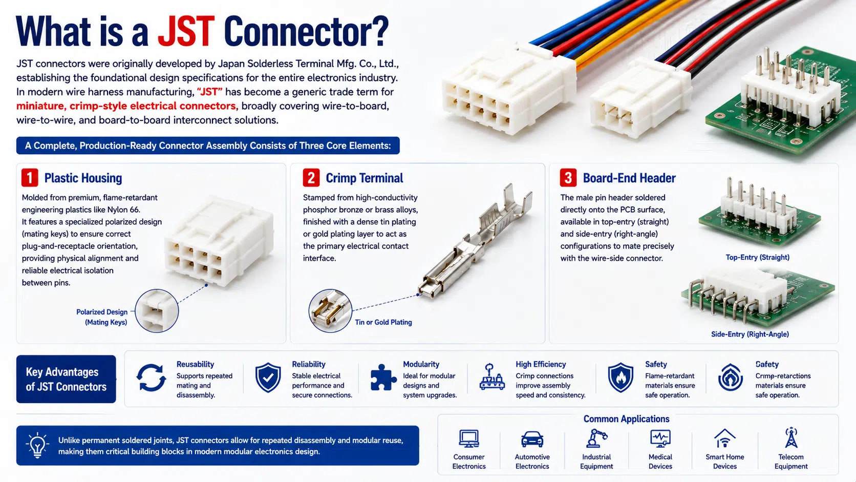
The housing positions and insulates the terminals and provides polarization or locking features. Housing material, color, circuit count, and latch design vary by series and part number. Do not assume that two housings with the same pitch will mate.
The terminal forms the electrical and mechanical connection to the wire. Terminal selection depends on the housing series, conductor size, insulation diameter, plating, application temperature, and required contact performance. The wire harness terminal selection guide explains conductor, plating, crimp, and inspection fundamentals.
Board headers may be vertical, right-angle, surface-mount, or through-hole. Verify circuit count, keying, mounting style, PCB footprint, mating direction, and allowable assembly height before releasing the PCB and harness drawings.
| Selection factor | Questions to answer | Why it matters |
|---|---|---|
| Interface type | Wire-to-board, wire-to-wire, or board-to-board? | Determines the connector architecture and available mating components |
| Pitch and envelope | What PCB pitch, mated height, width, and cable exit direction fit the enclosure? | Prevents mechanical interference and PCB footprint errors |
| Electrical load | What are the continuous current, voltage, duty cycle, and allowable temperature rise? | Controls terminal, wire, circuit count, and derating decisions |
| Wire construction | What conductor size, strand construction, insulation material, and outside diameter are used? | The terminal must match both conductor and insulation ranges |
| Retention | Is friction locking sufficient, or is a positive latch required? | Affects vibration resistance, service access, and unmating force |
| Environment | What temperature, humidity, dust, fluid, vibration, and mating-cycle conditions apply? | Determines whether an unsealed miniature connector is appropriate |
| Manufaktur | Are the approved applicator, hand tool, inspection method, and replacement terminals available? | Prevents unreliable crimps and supply-chain substitutions |
The table below is a practical orientation guide. Pitch values identify the family layout, but electrical ratings and wire ranges can vary by terminal, circuit count, wire, ambient temperature, and product revision. Confirm every production selection against the current JST datasheet for the exact part number.
| Series | Nominal pitch | Typical interface | Locking approach | Common use cases |
|---|---|---|---|---|
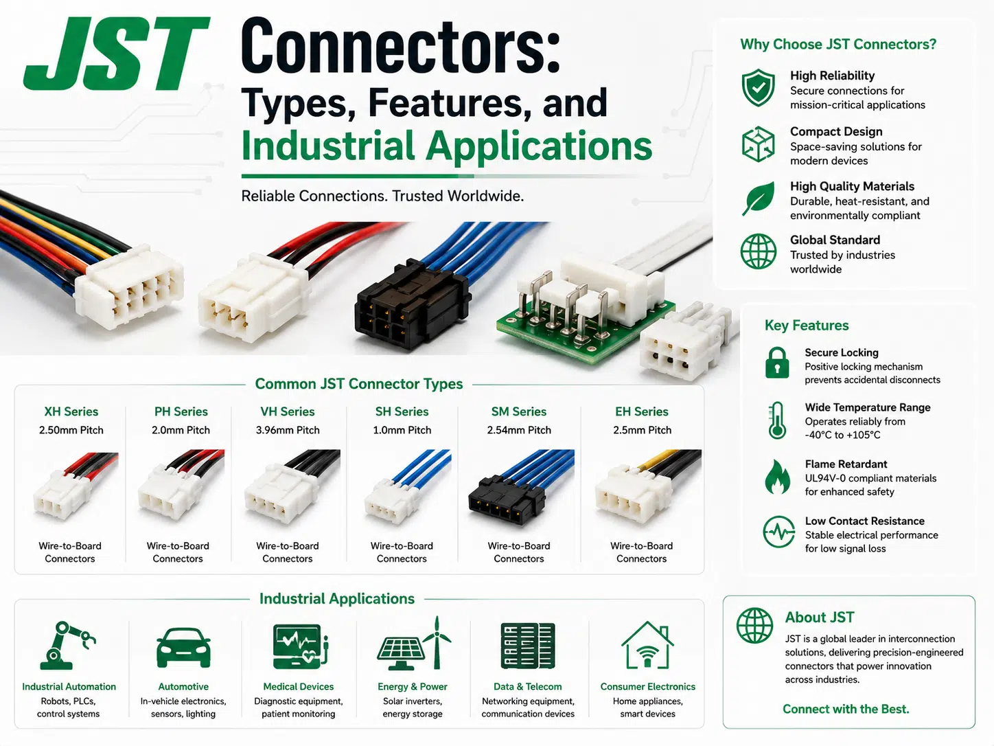
| SH | 1,0 mm | Wire-to-board | Friction lock | Compact sensors, cameras, and space-constrained electronics |
| GH | 1,25 mm | Wire-to-board | Positive lock | Compact equipment requiring stronger retention |
| ZH | 1,5 mm | Wire-to-board | Friction lock | Small consumer and industrial electronics |
| PH | 2,0 mm | Wire-to-board | Friction lock | Battery leads, displays, controls, and compact devices |
| PA | 2,0 mm | Wire-to-board | Positive lock | Applications needing a compact latched connection |
| XH | 2,5 mm | Wire-to-board | Friction lock | Appliances, control boards, and general electronic equipment |
| EH | 2,5 mm | Wire-to-board | Friction lock | Low-profile board connections and control equipment |
| RCY | 2,5 mm | Wire-to-wire | Locking housing | Two-circuit power and battery connections |
| SM | 2,5 mm | Wire-to-wire | Positive lock | LED, appliance, and detachable cable connections |
| VH | 3,96 mm | Wire-to-board | Positive lock | Larger wire and higher-load board connections |
Pitch is only one dimension. PH and XH families differ in pitch, terminal design, housing geometry, header pins, latch features, and PCB footprint. A PH housing should not be forced onto an XH header, and a terminal approved for one series should not be inserted into another housing.
For replacement or reverse-engineering work, record the manufacturer logo, series marking, circuit count, pitch, housing dimensions, latch position, terminal shape, wire size, and header orientation. When identification remains uncertain, obtain the mating component drawing or replace both sides with a fully documented connector system.
Connector ratings are not universal values attached to a series name. Use the official datasheet for the exact housing, terminal, and header combination. Check:
If a datasheet gives values under laboratory conditions, do not copy them directly into the system specification without considering enclosure temperature, bundling, duty cycle, ventilation, PCB limits, and safety margins.
Reliable performance depends on the terminal, wire, applicator, setup, and inspection method working as a controlled system. There is no single crimp-height or compression-ratio value that applies to every JST series.
For a broader production workflow, review the custom wire harness process dan wire harness quality-control overview.
Fine-pitch series can reduce PCB and harness size, but smaller contacts demand tighter wire preparation and tooling control. Confirm service access before choosing a connector that is difficult to unmate in a crowded enclosure.
JST connectors can be suitable inside protected equipment for sensors, displays, fans, control boards, and low-power circuits. Where dust, water, oil, high temperature, or repeated motion reaches the connector, evaluate a sealed or more robust alternative. The harness kawat industri page provides related application context.
Do not assume that a connector is automotive-qualified because it has a latch. Verify the exact series, environmental rating, material, vibration requirements, temperature class, sealing, and customer approval. Vehicle locations can impose very different conditions.
Connector selection should follow the equipment risk analysis, electrical requirements, cleaning environment, service procedure, and regulatory design controls. A miniature connector alone does not make a harness medical-grade.
| Problem | Likely cause | Recommended check |
|---|---|---|
| Intermittent circuit | Under-crimp, damaged strands, terminal not seated, connector movement | Inspect crimp section, terminal retention, strain relief, and mating condition |
| High resistance or heating | Overload, wrong terminal, poor crimp, contamination, damaged contact | Confirm part numbers, wire, load, crimp dimensions, and temperature rise |
| Housing will not mate | Wrong series, wrong circuit count, damaged keying, misaligned header | Compare both parts with manufacturer drawings |
| Terminal backs out | Locking lance damaged or terminal not fully inserted | Check insertion direction, seating click, and retention |
| Wire breaks near terminal | Cut strands, excessive flexing, poor strain relief, over-crimp | Review strip process, crimp section, routing, and support |
| Field corrosion | Moisture, incompatible environment, damaged plating, residue | Review sealing, cleaning, materials, and environmental exposure |
Use the exact manufacturer name and part number in the BOM. A supplier should not substitute a compatible-looking housing or terminal without engineering approval. If an alternate source is necessary, compare dimensional drawings, materials, plating, ratings, tooling, qualification evidence, and mating compatibility.
Mixing a genuine housing with an unapproved terminal can create a connection that looks acceptable but has incorrect retention or contact force. Treat the housing, terminal, header, and tooling as one approved system.
A perakitan kabel prototipe can confirm fit, pinout, routing, connector access, and manufacturability before production release.
No. Many manufacturers make similar-looking miniature connectors. Identify the brand, family, pitch, housing geometry, terminal, and mating header before ordering.
Not necessarily. Pitch does not define keying, pin dimensions, terminal geometry, latch design, or housing envelope.
Start with PCB space, mated height, wire range, electrical load, retention, and the approved PCB footprint. Then verify the exact part-number datasheets.
Do not design beyond the published rating. Apply system-level derating for ambient temperature, circuit loading, bundling, duty cycle, and enclosure conditions.
Use the terminal application specification and approved tooling instructions for the exact terminal and wire. A universal crimp height or compression ratio is not reliable.
They can be suitable for prototypes or service work when the correct approved tool and inspection criteria are used. Production requirements should be defined by the project quality plan.
Use the correct terminal, preserve the locking lance, insert it in the correct orientation, verify full seating, and provide strain relief so wire loads do not pull on the contact.
Use a connector system specifically rated for the required moisture, dust, fluid, temperature, and pressure conditions. For related design considerations, see the waterproof cable assembly guide.
Provide the exact connector part numbers, drawing, pinout, wire requirements, environment, inspection plan, and quantity range. Contact WIRES for a JST cable assembly requirements review.
 English English
 Vietnamese
 Indonesian
 Arabic
 Spanish