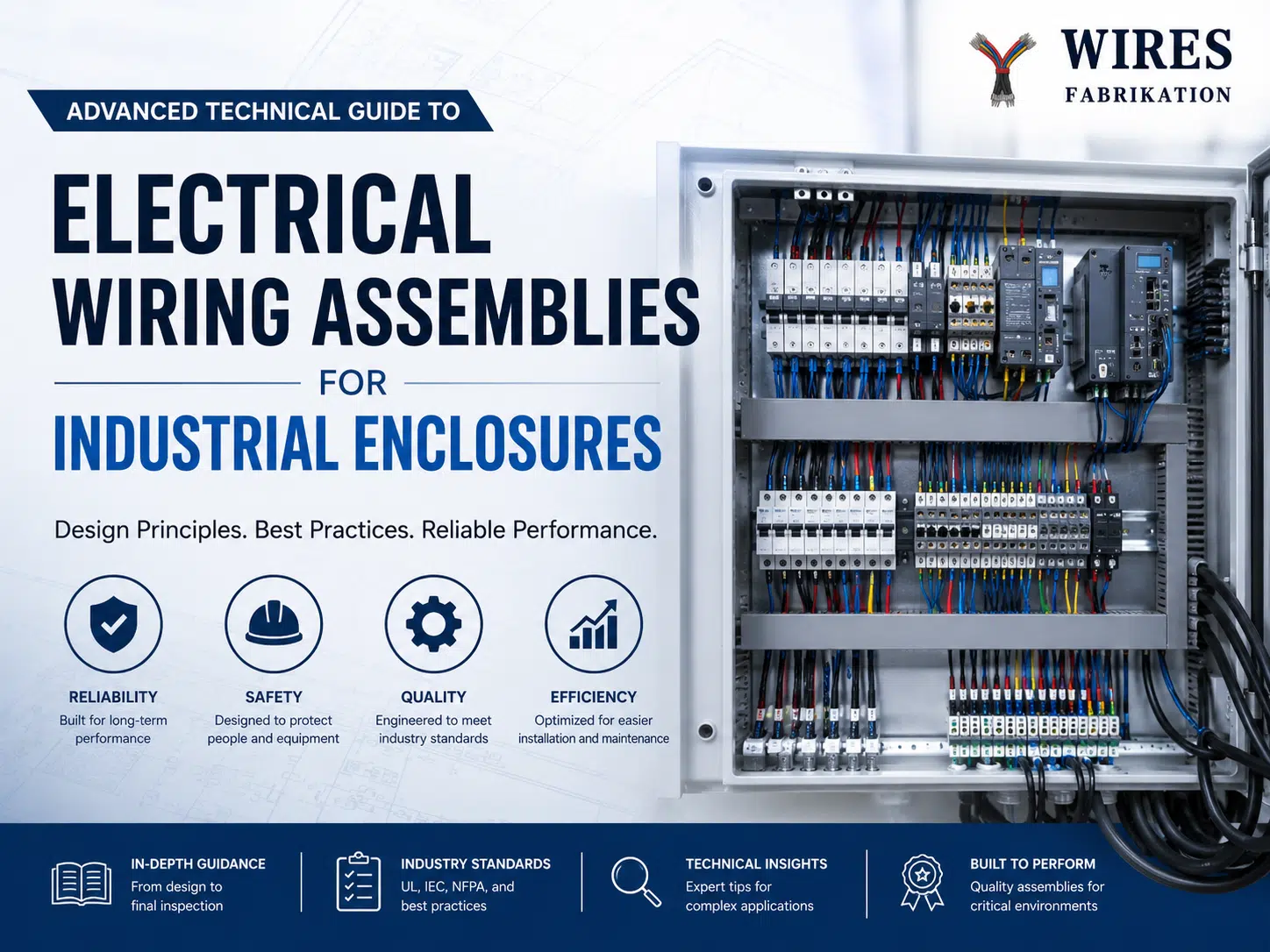
Quick answer: Industrial enclosure wiring is the controlled installation and interconnection of power, control, safety, communication, and grounding circuits inside a cabinet or control panel. Reliable assembly depends on an approved drawing, correct wire and terminal selection, physical separation, torque control, labeling, grounding, inspection, and project-specific testing.
No single color code, grounding topology, torque value, or test plan applies to every enclosure. Use the applicable customer specification, component instructions, electrical code, and machine or panel standard for the installation location.
Enclosure wiring normally connects power supplies, protective devices, contactors, relays, drives, PLCs, I/O modules, terminals, sensors, actuators, safety circuits, communication networks, and grounding points. The scope can include internal cabinet wiring, door-mounted components, field-terminal interfaces, cable entry, labels, and test documentation.
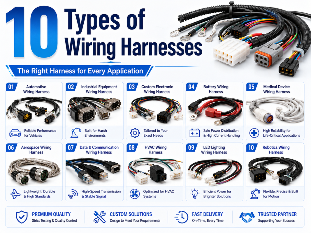
For related assembly options, review مجموعات الأسلاك الصناعية و wire harness vs. cable assembly guide.
| Document or input | What it controls |
|---|---|
| Electrical schematic | Circuit function, protective devices, terminals, conductor identification, and connection points |
| Panel layout | Component placement, DIN rail, wire duct, ventilation, access, and separation |
| Bill of materials | Approved wire, terminals, ferrules, labels, connectors, duct, and protective parts |
| Wiring table or point list | From-to connections, wire numbers, sizes, colors, and termination details |
| Standards list | Applicable code, panel, machine, customer, and installation requirements |
| Inspection and test plan | Visual, dimensional, continuity, dielectric, functional, and documentation requirements |
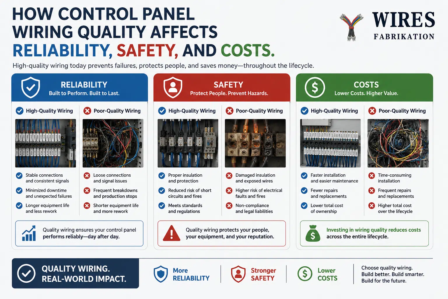
Resolve drawing conflicts and missing information before production. Field changes should follow an approved engineering-change process so the finished panel and as-built documentation remain consistent.
Conductor size must be based on circuit current, protective device, allowable voltage drop, ambient temperature, bundling, terminal rating, duty cycle, fault conditions, and the applicable code or equipment standard. Do not select wire size from current alone.
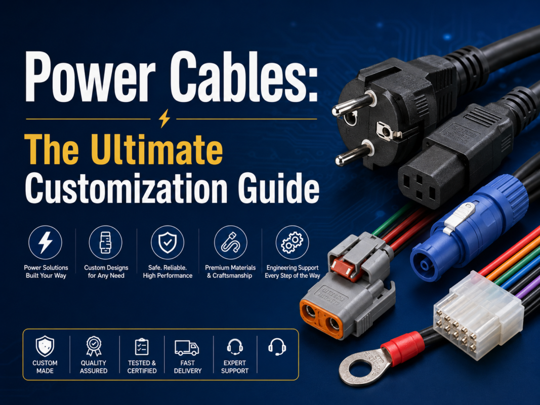
Insulation and jacket materials should match temperature, oil, chemicals, abrasion, flexing, flame, and installation requirements. For power-related selection factors, see the custom power cable guide.
Routing should reduce mechanical damage, heat exposure, electrical noise, and maintenance difficulty. The required spacing or barriers depend on voltage, signal type, EMC design, safety classification, component instructions, and the applicable standard.
Grounding is a system design decision. Protective bonding, functional grounding, signal reference, cable shields, and enclosure bonding have different purposes. A single-point, multi-point, or hybrid approach may be appropriate depending on frequency, equipment architecture, and the governing design.
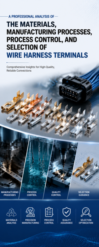
Terminations are common failure points because they combine electrical contact, mechanical retention, and installation variability. The wire harness terminal guide covers materials, plating, crimping, and validation in more detail.
Labels should match the schematic and remain readable in the operating environment. Define wire numbers, terminal identifiers, device tags, cable labels, voltage warnings, and replacement markings before production.
A controlled custom wiring process helps connect engineering decisions to repeatable production.
| Verification | Purpose | Application note |
|---|---|---|
| الفحص البصري | Confirm workmanship, routing, labels, damage, and component installation | Use the released drawing and defined acceptance criteria |
| Point-to-point continuity | Detect opens, shorts, and connection errors | Test coverage may be manual or automated depending on complexity |
| Protective-bonding check | Verify required conductive parts are bonded | Use the method and limit from the applicable standard or test plan |
| Insulation or dielectric test | Assess circuit isolation when required | Confirm components can tolerate the selected test voltage and method |
| Power-up and functional test | Check power distribution, I/O, interlocks, safety functions, and controls | Use an approved procedure and suitable risk controls |
| Thermal review | Identify unexpected heating under defined load conditions | State load, duration, ambient conditions, and acceptance criteria |
Qualification tests, production acceptance tests, and site commissioning are separate activities. The project documents should define who performs each test and what records are required. See the wire harness quality-control overview.
| Problem | Risk | Corrective direction |
|---|---|---|
| Overfilled wire duct | Heat buildup, damaged insulation, difficult maintenance | Review fill, routing, conductor sizing, and future capacity |
| Mixed power and signal wiring | Noise coupling or unsafe separation | Apply the project EMC and separation requirements |
| Incorrect terminal preparation | High resistance, loose strands, terminal damage | Use matched terminals, tooling, strip length, and inspection |
| Uncontrolled tightening | Loose or damaged terminal connection | Follow component instructions and the project torque-control plan |
| Missing or inconsistent labels | Wiring errors and slow troubleshooting | Reconcile labels with the released and as-built documents |
| Poor bonding or shield termination | Safety, EMC, or signal problems | Review protective bonding and functional grounding separately |
| Unapproved field modification | Documentation mismatch and hidden risk | Use formal change approval and update the as-built package |
Possible references include UL 508A for industrial control panels in applicable North American programs, NFPA 79 for industrial machinery, IEC 60204-1 for electrical equipment of machines, and customer or local electrical requirements. Their applicability depends on jurisdiction, product scope, certification plan, and contract.
Referencing a standard in an article does not mean every WIRES project or facility holds that certification. Request current certificates, scope, and project evidence when certification is a purchasing requirement.
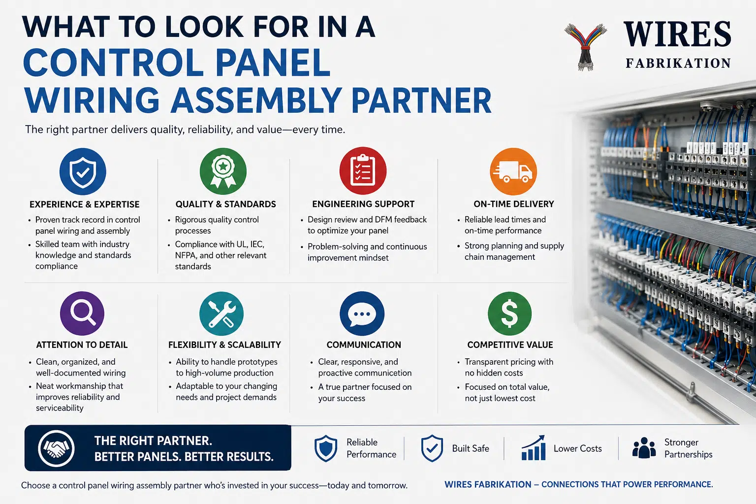
A prototype cable assembly or wiring set can help confirm routing, interfaces, terminal access, and documentation before production release.
Design defines circuits, protection, layout, components, and requirements. Wiring assembly builds and connects the approved design. Responsibility for each activity should be clear.
Use the applicable standard, customer specification, and released drawing. Color conventions vary by jurisdiction, voltage, circuit function, and company practice.
Use the terminal or component manufacturer’s specified value and method. There is no universal torque for all terminals.
Separation depends on voltage, frequency, circuit sensitivity, shielding, barriers, routing length, and the applicable EMC and safety requirements.
No. Protective bonding and signal grounding serve different purposes. Single-point, multi-point, or hybrid grounding should follow the equipment and EMC design.
Not necessarily. The applicable standard, components, design, and test plan determine whether dielectric, insulation-resistance, bonding, continuity, and functional tests apply.
Use documented issue resolution and engineering-change approval, then update drawings, BOMs, wiring lists, software references, and as-built records.
No. Wiring is one part of the complete electrical and mechanical system. Reliability also depends on design, components, environment, software, protection, installation, and maintenance.
Provide the schematic, layout, BOM, standards, wiring list, inspection plan, and scope of responsibility. Contact WIRES for an industrial enclosure wiring review.
 English English
 Vietnamese
 Indonesian
 Arabic
 Spanish