



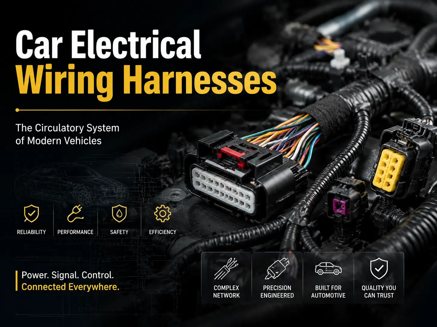
Quick answer: A car electrical wiring harness is the organized network of wires, terminals, connectors, splices, seals, protection, and labels that distributes power and signals throughout a vehicle. Reliable design depends on circuit load, voltage drop, temperature, vibration, moisture, routing, connector retention, electromagnetic compatibility, and vehicle-specific validation.
A warning lamp, intermittent window, sensor fault, battery drain, or no-start condition can involve the harness, but the harness should not be blamed before power supply, grounds, fuses, modules, connectors, and diagnostic trouble codes are checked. This guide explains how automotive harnesses are designed, why they fail, how to diagnose them, and what information is needed for replacement or custom production. Readers new to the subject can start with the basic components of a wire harness.
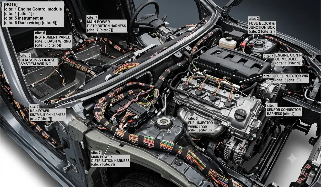
A car electrical wiring harness connects the battery, fuse and relay centers, electronic control units, sensors, actuators, lighting, motors, switches, infotainment equipment, safety systems, and communication networks. It keeps individual conductors routed, identified, protected, and terminated as one installable assembly.
A modern vehicle normally uses several sub-harnesses rather than one single bundle. Typical sections include the engine, dashboard, body, doors, roof, chassis, lighting, battery, and high-voltage harnesses. The exact architecture varies by vehicle platform. For a broader comparison, see the guide to common types of wiring harnesses.
| Vehicle harness zone | Typical circuits | Main design risks | Information to specify |
|---|---|---|---|
| Engine compartment | Injectors, ignition, sensors, alternator, cooling equipment | Heat, vibration, fluids, abrasion, connector sealing | Temperature profile, fluid exposure, clamp points, connector series |
| Instrument panel | Displays, controls, HVAC, infotainment, communication buses | Dense routing, noise coupling, assembly access, squeak and rattle | Package space, branch dimensions, grounding and network requirements |
| Body and doors | Locks, windows, mirrors, seats, interior lighting | Repeated flexing, hinge routing, water entry, service damage | Motion path, bend control, grommets, strain relief, mating interfaces |
| Chassis and exterior | Wheel-speed sensors, lighting, pumps, trailer and underbody circuits | Water, salt, stone impact, mud, abrasion, pressure washing | Ingress requirement, protection method, mounting and inspection access |
| Battery and high-current distribution | Starter, charging, fuse distribution, electric drives | Voltage drop, heating, short-circuit energy, mechanical strain | Current profile, conductor size, protection device, terminal and torque requirements |
| High-voltage electric vehicle system | Traction battery, inverter, motor, charger, HVAC compressor | Electric shock, insulation damage, shielding, interlock integrity | OEM safety specification, voltage class, service procedures, validation plan |
Wire size should be calculated from continuous and peak current, allowable voltage drop, circuit length, ambient temperature, bundle size, duty cycle, conductor material, and protective-device rating. A single current-to-wire-size chart is not enough because installation conditions change the allowable load.
Power circuits, low-level sensor lines, communication pairs, coaxial cables, and safety-related circuits may need different conductor and routing rules. The schematic should identify circuit function, load, grounding point, shielding, splice location, fuse or breaker, and permitted voltage drop.
Automotive primary-wire families such as TXL, GXL, SXL, and other SAE or OEM wire types differ in wall thickness, insulation material, flexibility, abrasion behavior, and temperature rating. The correct choice must be confirmed from the current wire specification and manufacturer datasheet. The wire name alone does not prove suitability for a particular engine-bay or body application.
ISO 6722, SAE J1128, and the ISO 19642 series may be relevant to road-vehicle cables. Their applicability depends on voltage class, conductor construction, market, vehicle manufacturer, and drawing requirements. Citing one of these standards is not the same as claiming that WIRES or a finished harness is certified to it.
A connector system includes more than the plastic housing. Terminal part number, plating, conductor crimp, insulation support, wire seal, cavity plug, terminal-position assurance, connector-position assurance, backshell, strain relief, and mating interface all affect performance.
The terminal must match the wire conductor area, insulation diameter, plating system, mating terminal, and approved applicator. Review the detailed guide to automotive wire harness terminals and crimping. For compact board and low-current interfaces, the JST connector selection guide shows why housing, terminal, pitch, and header must be treated as one system.
Routing should keep the harness away from exhaust components, sharp edges, moving mechanisms, pinch points, standing water, and service tools. Clips, channels, grommets, conduit, braided sleeving, tapes, boots, heat shields, and overmolds are selected for the local hazard rather than applied uniformly.
Branch lengths and clip positions need realistic tolerances. A harness that is too short can load terminals and seals; one that is too long can rub, sag, or enter a moving area. Door and tailgate sections need controlled flex geometry and strain relief, not simply softer wire.
Sealed connectors are appropriate only when the complete connector system is assembled within its specified wire range and test condition. Unused cavities, damaged seals, incorrect strip length, missing secondary locks, poorly supported splices, and capillary paths can still allow moisture to enter.
An IP rating applies to the exact product configuration and test conditions. It should not be used as a general promise that every part of a vehicle harness is waterproof. See waterproof cable assembly design considerations for sealing and overmolding decisions.
CAN, LIN, Ethernet, camera, RF, audio, and sensor circuits can be affected by pair geometry, impedance, shield termination, grounding, connector transitions, stubs, and proximity to switching power circuits. Twisting or shielding should follow the interface and vehicle EMC design, not a universal rule.
Hybrid harnesses that combine power and data require a thermal and noise-coupling review. The interface specification should define controlled-impedance circuits, twist requirements, shield coverage or termination, drain-wire connection, and permitted untwist at terminals.
| Failure mode | Possible symptoms | Useful checks | Corrective action |
|---|---|---|---|
| Chafed or cut insulation | Intermittent fuse opening, short to ground, sensor faults | Inspect contact points, flex the branch carefully, check circuit isolation | Correct routing and protection; repair or replace to an approved procedure |
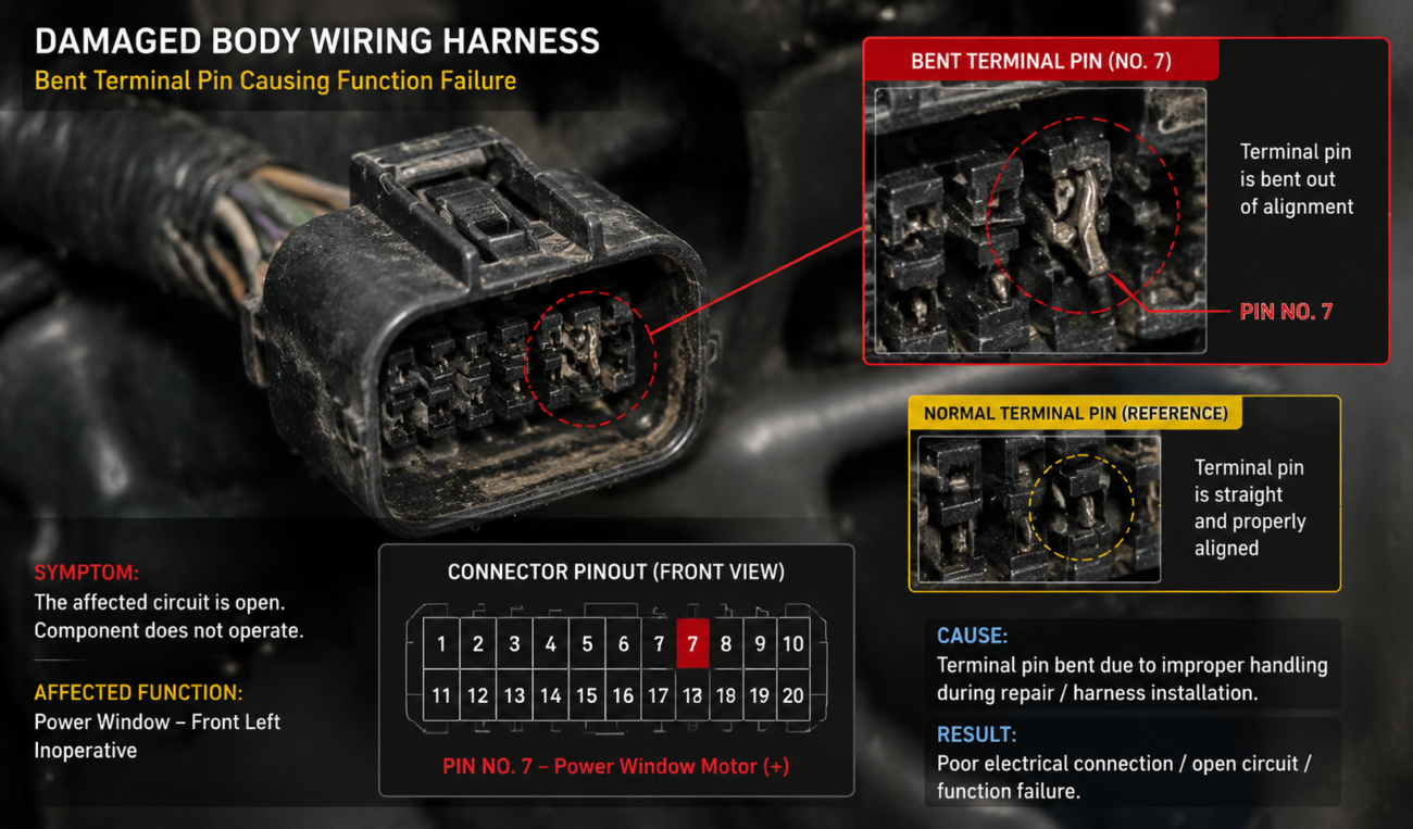
| Loose or backed-out terminal | Intermittent operation, heat, voltage drop, communication fault | Check terminal position, secondary lock, drag and retention using approved tools | Replace damaged terminals or housings and verify the crimp process |
| Corrosion or water ingress | High resistance, unstable sensor signal, green deposits, repeated faults | Find the ingress path, inspect seals and splices, measure under load | Replace affected components and correct the sealing or routing cause |
| Broken conductor inside insulation | Fault changes with door, seat, steering, or tailgate movement | Monitor the circuit while reproducing the motion; inspect high-flex zones | Replace or repair the flex section using a vehicle-approved method |
| اتصال أرضي ضعيف | Multiple unrelated faults, dim lighting, unstable module behavior | Perform a loaded voltage-drop test and inspect ground fasteners and surfaces | Restore the specified ground path and corrosion protection |
| Unapproved splice or accessory tap | Battery drain, overheating, noise, intermittent aftermarket equipment | Compare wiring with the approved schematic and inspect added circuits | Remove or redesign the modification with correct protection and interfaces |
| Incorrect repair terminal or wire | Repeat failure, poor retention, sealing loss, localized heating | Verify part numbers, wire range, plating, tool, seal, and repair instructions | Rework with approved materials and validate the repaired circuit |
High-voltage electric-vehicle circuits require trained personnel, approved isolation procedures, personal protective equipment, and vehicle-specific service information. Do not probe or repair an orange high-voltage harness using general low-voltage methods.
| Option | Appropriate when | Main limitations |
|---|---|---|
| Localized repair | Damage is limited, access is practical, and an approved repair method exists | Must use compatible wire, terminals, seals, splice protection, and routing |
| Sub-harness replacement | A door, sensor, lighting, or equipment branch is available separately | Confirm connector revisions, option codes, branch lengths, and mating parts |
| Complete replacement harness | Damage is widespread, insulation is degraded, or prior modifications are extensive | Installation labor, trim removal, configuration differences, and obsolete parts |
| Custom reproduction or conversion harness | Restoration, engine swap, special vehicle, prototype, or unavailable original part | Requires complete electrical documentation, interfaces, routing, and validation |
A custom harness should not be copied only from an old sample when the sample may contain repairs or undocumented changes. Combine the sample with the vehicle schematic, connector identification, pinout, routing dimensions, option list, and intended electrical load. The OEM wiring harness overview و customized wire harness process explain how drawings, BOMs, samples, and approvals should be controlled.
Accessory circuits should use a defined power source, suitable fuse or circuit protection, correct conductor size, reliable grounding, and connectors intended for the environment. Avoid cutting safety-related circuits or loading an existing circuit without confirming its design capacity.
For stereo replacement, wire colors are only a starting reference. Vehicle year, model, trim, amplifier, data-bus interface, and previous modifications must be verified. See the car audio wire harness color guide for a cautious identification workflow.
Plug-in adapter harnesses can preserve the original vehicle wiring, but they still require correct pinout, terminal quality, strain relief, and circuit protection. A mechanically compatible connector is not proof of electrical compatibility.
| Reference | Typical subject | How to use it correctly |
|---|---|---|
| ISO 6722 series | Road-vehicle low-voltage cables | Specify the applicable part, edition, cable type, size, and test requirements |
| ISO 19642 series | Road-vehicle cable requirements, including higher-voltage applications | Confirm scope, voltage class, construction, and OEM additions |
| SAE J1128 | Low-voltage primary cable types | Verify the current revision and exact wire type on the drawing |
| USCAR-2 | Electrical connector system performance | Use only when invoked by the customer or program specification |
| USCAR-21 | Crimped electrical terminal performance | Match the terminal, wire, tooling, methods, and acceptance limits |
| IPC/WHMA-A-620 | Cable and wire harness workmanship | State the revision, class, amendments, and customer-specific criteria |
These are industry references, not automatic statements of WIRES certification or product compliance. Evidence should match the actual claim: a current certificate and scope for a management system, a component datasheet or recognition record for a material, and a test report for a specific harness configuration.
No universal crimp height, pull force, resistance, dielectric voltage, or sampling rate applies to every automotive harness. Limits must come from the approved terminal-wire combination, customer specification, component supplier data, and applicable standard. The wire harness quality-control guide provides a broader inspection framework.
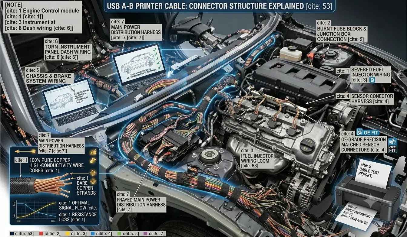
For a new design or conversion, a تجميع كابل النموذج الأولي can be used to verify fit, routing, connector access, pinout, and assembly sequence before production release. The comparison of wire harnesses and cable assemblies can also help define the required protection and construction.
Possible symptoms include intermittent electrical operation, repeated fuse opening, communication faults, unstable sensor readings, battery drain, heat at a connector, or a fault that changes with vibration or movement. These symptoms are not proof by themselves; power, grounds, modules, and connected equipment must also be tested.
Localized damage may be repairable when the vehicle manufacturer provides an approved method and the correct wire, terminal, seal, splice, tooling, and protection are available. Widespread heat, fluid, corrosion, fire, or previous modification damage may justify sub-harness or complete replacement.
Not automatically. They can differ in insulation construction, wall thickness, diameter, flexibility, temperature performance, abrasion behavior, and connector-seal compatibility. Use the exact wire required by the current drawing or obtain engineering approval for a substitute.
No. The rating applies to the tested connector configuration and conditions. Correct terminals, wire seals, cavity plugs, backshells, mating, assembly, routing, splices, and overmolds still affect the complete harness.
No. Test voltage and method must be appropriate for the circuit and connected components. Continuity and pinout checks are common, while insulation or dielectric tests are used only when required by the approved specification and with sensitive devices protected.
Provide the schematic, pinout, connector and terminal part numbers, wire requirements, branch dimensions, routing, environmental conditions, standards, tests, quantities, and revision status. If an old sample is supplied, identify whether it is known-good, damaged, repaired, or modified.
A reliable automotive harness starts with complete circuit and installation information, not a generic “automotive-grade” label. Send the drawing, schematic, sample details, connector list, operating environment, and test requirements through the WIRES contact page for a project-specific review.
 English English
 Vietnamese
 Indonesian
 Arabic
 Spanish


