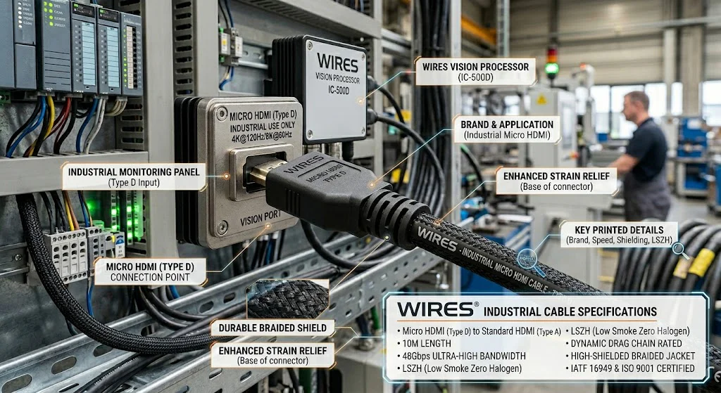
An industrial Micro HDMI cable connects an HDMI Type D source or display to compatible video equipment while addressing the routing, retention, electromagnetic, environmental, and validation needs of the installed system. The connector is compact, but the cable still carries high-speed differential video data, clocking, control, device-detection, and power-related functions defined by the HDMI interface.
Reliable selection begins with the exact source and sink devices, supported HDMI features, video format, cable length, connector direction, retention method, routing, environmental exposure, and verification plan. A consumer cable may work in some equipment, but an industrial or medical project needs documented requirements rather than a generic rugged or medical-grade label.
| Decision | What to confirm | Why it matters |
|---|---|---|
| Connector interface | Type D source or sink, mating orientation, Type A or other opposite end | Similar connector shapes are not interchangeable |
| Video and HDMI features | Resolution, refresh rate, color format, HDR, audio, CEC, ARC/eARC, Ethernet channel, HDCP | Equipment support and cable channel margin vary |
| Panjang kabel | Installed route, adapters, extensions, panel feedthroughs, receiver margin | There is no universal passive-cable maximum |
| Conversion | Same HDMI protocol or active conversion to VGA, USB, DisplayPort, or another interface | Connector adapters do not automatically convert protocols |
| Mechanical design | Retention, strain relief, bend radius, vibration, service cycles, routing space | Type D connectors are compact and sensitive to cable leverage |
| Environment | Temperature, fluids, cleaning, abrasion, UV, ingress, medical or industrial zone | Material and sealing evidence must match actual exposure |
| Validation | Continuity, wiring, signal or functional tests, motion and environmental tests | Basic continuity cannot prove high-speed video performance |
For a broader mixed-signal and industrial video framework, see the industrial AV cable assembly guide. DVI-specific source and display decisions are covered in the medical and industrial DVI cable guide.
Micro HDMI is HDMI Type D, a compact 19-contact interface in the HDMI connector family. It is used on some cameras, embedded computers, portable instruments, displays, industrial controllers, imaging modules, and compact medical equipment. The opposite cable end may use Type D, standard Type A, Mini HDMI Type C, or another interface through a compatible active device.
Type D preserves the HDMI electrical functions in a smaller mechanical package. This does not mean every Micro HDMI source supports every HDMI feature or video format. The source, sink, firmware, chipset, operating system, and cable channel must all support the intended function.
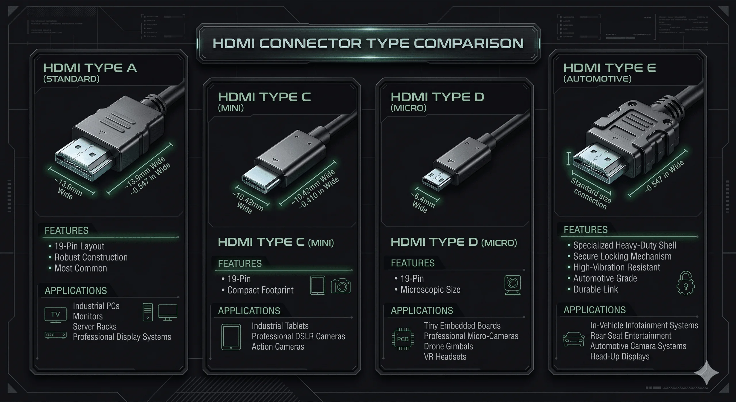
| HDMI connector | Common description | Project use |
|---|---|---|
| Type A | Standard HDMI | Displays, computers, cameras, equipment panels |
| Type C | Mini HDMI | Some cameras, portable and embedded devices |
| Tipe D | Micro HDMI | Compact cameras, modules, instruments, embedded equipment |
The connector type identifies the mechanical interface, not the supported resolution, HDMI revision, cable length, or environmental rating. Document the equipment model and interface capabilities.
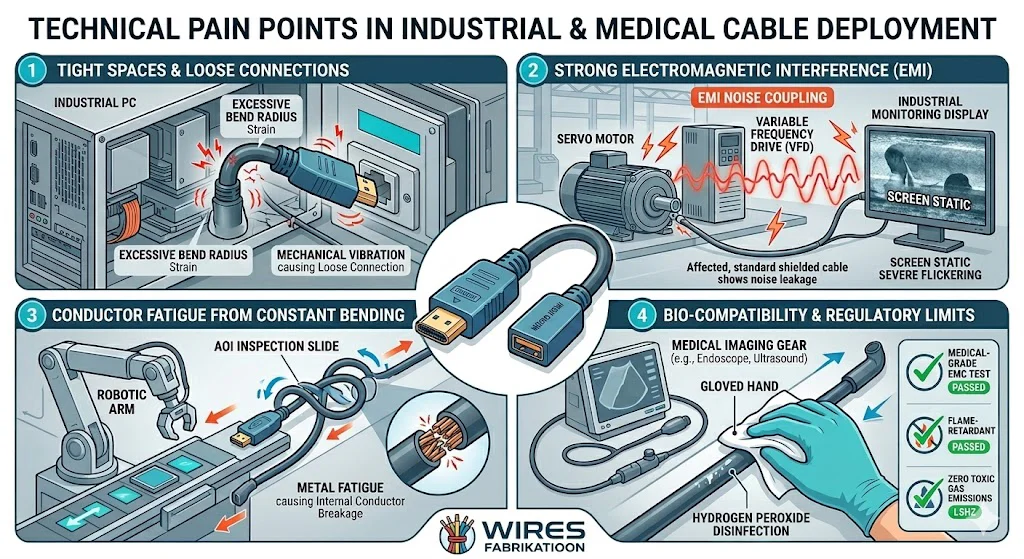
A stiff or unsupported cable can apply leverage to the small Type D connector and equipment port. Repeated movement, side loading, vibration, or pulling can damage the plug, cable termination, panel mounting, or circuit-board connector. Use suitable routing, support, strain relief, and retention where the equipment permits it.
HDMI carries high-speed differential channels. Cable loss, pair skew, impedance discontinuities, crosstalk, connector transitions, adapters, and source or receiver margin affect link reliability. A cable can pass continuity while failing at the intended video mode.
Shield construction, connector-shell termination, equipment chassis, power supplies, cable routing, and nearby switching sources influence EMC. More shielding does not automatically fix a grounding or enclosure problem.
Industrial equipment may expose cables to oil, coolant, abrasion, vibration, temperature, or repeated handling. Medical and laboratory equipment may introduce cleaning chemicals, disinfection, sample or reagent zones, compact routing, and risk-management requirements. The exact zone and exposure must be defined.
An HDMI connection is more than a set of video conductors. The source and sink exchange capability information and may use content-protection handshakes. A black screen, limited resolution, or intermittent image can result from cable channel loss, unsupported formats, adapter direction, firmware, power, EDID handling, HDCP compatibility, or equipment settings.
| Compatibility item | Questions to record |
|---|---|
| Source output | Which HDMI formats and features does the device actually support? |
| Sink input | Which resolution, refresh, color, HDR, audio, and protection modes are accepted? |
| Arah | Which device is the source and which is the display or capture sink? |
| Adapters | Are they passive pin adapters or active converters, and are they directional? |
| Daya | Does an active adapter need HDMI power, USB power, or a separate supply? |
| Firmware and drivers | Are software, operating system, or device settings required? |
Validate the intended source, cable, adapters, feedthroughs, and sink as a complete channel. A general HDMI label on each component does not guarantee that the combination supports every feature.
There is no universal passive Micro HDMI cable length. The limit depends on video format, channel rate, conductor geometry, dielectric, cable diameter, connector transitions, adapters, source output, receiver equalization, temperature, routing, and manufacturing variation.
A practical channel review should include:
When a long passive channel lacks margin, options may include a shorter route, fewer transitions, a different cable construction, an active cable, repeater, extender, or optical system. The active device must support the required HDMI functions and installation environment.
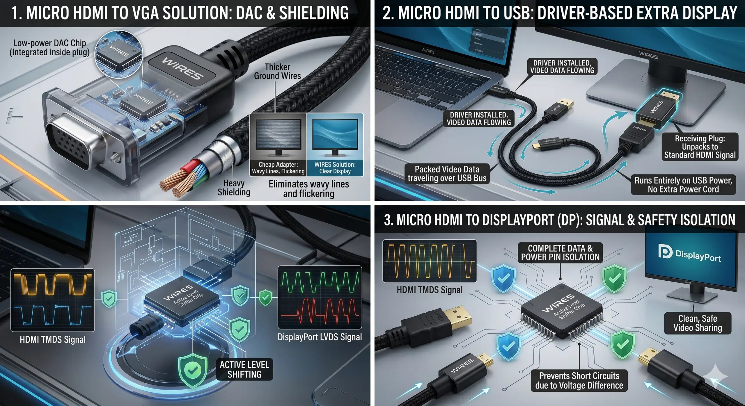
| Koneksi | Passive or active? | Key checks |
|---|---|---|
| Micro HDMI to standard HDMI | Often passive when both ends use the HDMI protocol | Direction, cable channel, equipment features, connector orientation |
| HDMI to DVI digital video | May be passive for compatible digital video modes | Connector type, direction, audio limitations, HDCP, resolution, equipment support |
| HDMI to VGA | Requires active digital-to-analog conversion | Direction, supported formats, power, scaling, audio, EDID behavior |
| USB to HDMI display output | Requires an active graphics or display adapter | USB version, driver or OS support, direction, power, performance, display limits |
| HDMI capture through USB | Requires an active video-capture device | Input/output direction, capture format, latency, software, power |
| HDMI to DisplayPort | Often requires active conversion; direction matters | Source and sink type, adapter direction, power, resolution, feature support |
| DisplayPort to HDMI | May use passive or active adaptation depending on the source and mode | Source capability, direction, adapter specification, display requirements |
A cable manufacturer should not claim a passive cable converts incompatible protocols. When active electronics are required, specify the converter chipset or product, power, firmware, direction, supported modes, EMC, temperature, and qualification separately from the cable assembly.
Micro HDMI does not use the positive locking mechanisms found on many industrial circular or threaded connectors. Retention options depend on the device and may include equipment brackets, panel clamps, cable clips, backshells, screw-retained adapters, docking hardware, or enclosure-level strain relief.
| Mechanical factor | Design input |
|---|---|
| Cable stiffness | Diameter, jacket, shielding, bend radius, route, temperature |
| Connector load | Cable weight, side force, vibration, service movement, unsupported length |
| Port support | PCB connector, panel, bracket, enclosure, mating access |
| Layanan | Mating frequency, replacement, labeling, inspection, protective cap |
| Strain relief | Boot, clamp, clip, heat shrink, overmold, enclosure support |
An overmolded cable assembly can provide controlled cable-entry geometry and strain relief when the connector, jacket, resin, mold, and adhesion are compatible. It does not automatically make the HDMI plug waterproof or suitable for every flexing condition.
HDMI high-speed channels rely on controlled differential pairs. Pair geometry, twist, dielectric, shielding, drain-wire routing, connector transition, and pair-to-pair skew matter. The complete equipment installation also affects common-mode noise and emissions.
For systems that combine HDMI with power, audio, control, or other media channels, review the industrial AV cable design guide. Multi-channel audio routing is covered separately in the kabel penghubung guide.
Some equipment routes HDMI with separate power, USB, trigger, control, or data circuits. Combining these functions can reduce installation work but increases the need for separation, grounding, thermal, fault, connector, and service planning.
Document voltage, current, startup load, conductor size, voltage drop, insulation, protection, and pin sequencing for any power circuits. The custom power cable guide provides related selection inputs. Do not assume the HDMI cable itself can power external conversion electronics beyond the limits of the defined interface and device.
| Exposure | Evidence or design response |
|---|---|
| Oil, coolant, or cleaning fluid | Exact chemical compatibility or representative exposure test |
| Temperature | Complete cable and connector data for fixed and moving conditions |
| Getaran | Port support, cable strain, retention, representative equipment test |
| Repeated motion | Motion type, bend radius, travel, speed, torsion, failure criteria |
| Abrasion or sharp edges | Sleeving, conduit, grommets, clamps, routing protection |
| Dust or moisture | Complete enclosure and mated-interface protection plan |
| UV or outdoor use | Material evidence, weather protection, drainage, connector sealing |
A cable marketed as industrial does not automatically satisfy a specific machine or installation code. The drawing should identify the exact materials and validation conditions.
Medical requirements depend on intended use, equipment classification, patient or operator contact, cleaning, disinfection, sample or reagent exposure, EMC, insulation, risk management, and market. A Micro HDMI cable cannot independently make a medical device compliant or guarantee image quality.
An internal cable may need compact routing, connector retention, low particulate generation, defined materials, service access, and controlled EMC. These requirements differ from a patient-accessible or externally handled cable.
Repeated connection, pulling, coiling, cleaning, and accidental side load may dominate the design. The equipment should support the connector and cable so the PCB port is not the main strain-relief element.
Specify the chemical or process, concentration, temperature, exposure time, drying, mating state, and acceptance criteria. A jacket or resin datasheet does not automatically qualify the finished connector assembly.
For analyzer zones, sample and reagent boundaries, EMC, cleaning, motion, and traceability, see the IVD equipment cable assembly guide. Cable evidence contributes to the complete instrument validation but does not replace it.
| Specification field | Information to provide |
|---|---|
| Equipment | Source, sink, model, firmware, interface direction, installation zone |
| Video | Resolution, refresh, color, HDR, audio, HDCP, CEC, ARC/eARC, required features |
| Konektor | Type D, Type A, Type C, orientation, gender, panel or equipment mating |
| Channel | Length, tolerance, adapters, feedthroughs, extensions, active devices |
| Mekanis | Bend radius, routing, vibration, flexing, retention, strain relief, service cycles |
| Environment | Temperature, fluids, cleaning, UV, ingress, abrasion, medical or industrial zone |
| Bahan | Cable construction, jacket, shield, overmold, labels, restricted substances |
| Validation | Wiring, continuity, functional video modes, signal tests, mechanical and environmental tests |
| Documentation | Drawing, bill of materials, inspection report, traceability, change control |
Review the available custom cable and interconnect options and follow the customized cable development process to freeze requirements, drawings, samples, and production controls. The cable assembly specification guide provides additional RFQ inputs.
A prototype should confirm connector orientation, fit, routing, length, retention, strain relief, labels, source/sink compatibility, and the required video modes. Use a prototype Micro HDMI cable assembly before committing to special cable, overmolds, brackets, or production fixtures.
Project-dependent validation may include:
Qualification testing and production acceptance serve different purposes. Define the sample, method, equipment, setup, limits, operating mode, and report format for each.
Production controls may include approved cable and connector part numbers, cut length, pair and shield handling, solder or termination process, connector orientation, overmold or strain-relief geometry, visual inspection, continuity, and functional testing. The exact controls should follow the released drawing and project risk.
Review the cable assembly quality approach and request project-specific inspection and test evidence. Unsupported claims about ISO certification, universal high-speed performance, or complete medical compliance should not replace product records.
| Gejala | Possible causes | Useful checks |
|---|---|---|
| No image | Wrong direction, unsupported adapter, open circuit, equipment setting, HDCP or EDID issue | Source/sink verification, known-good channel, adapter direction, wiring test |
| Intermittent black screen | Marginal channel, connector movement, cable damage, power or handshake issue | Required-mode test, movement check, connector and adapter inspection |
| Limited resolution or refresh | Source or sink limit, cable loss, adapter limit, driver or firmware setting | Equipment capabilities, direct connection, format and software review |
| Sparkles or image errors | High-speed channel loss, reflections, skew, connector or bend damage | Shorter known-good cable, route inspection, signal test if specified |
| Connector damage | Side load, unsupported cable, tight bend, vibration, frequent handling | Port support, strain relief, routing, retention, service process |
| Cleaning or fluid damage | Material incompatibility, liquid entry, seal or overmold damage | Fluid identity, exposure history, material and interface inspection |
For a display interface project that needs a controlled cable assembly, defined pinout, connector retention, routing, or validation plan, review custom display cable assemblies.
No. Micro HDMI is Type D and Mini HDMI is Type C. They are different connector sizes and do not mate directly.
Yes, a passive cable or adapter can connect Type D to Type A when both devices use compatible HDMI interfaces and the complete channel supports the required features and video mode.
No. HDMI is digital and VGA is analog, so active conversion is required. Confirm direction, power, supported formats, audio needs, and EDID behavior.
Not through a passive cable. USB display output requires an active graphics adapter, while HDMI capture through USB requires an active capture device. Direction, drivers, software, and power matter.
There is no universal maximum. The allowable length depends on video mode, cable construction, source and receiver margin, adapters, feedthroughs, bends, temperature, and required features.
It may be suitable when the equipment interface, intended use, materials, cleaning, EMC, mechanical design, risk controls, and validation requirements are defined and met. A medical-grade label alone is not enough.
Testing should follow the project specification and may include dimensions, workmanship, wiring, continuity, shield checks, required video modes, signal tests, pull, flex, vibration, temperature, fluid, cleaning, or ingress tests.
Send the source and sink models, required video modes and features, cable length, connector orientation, adapters, routing, retention, environment, cleaning conditions, and validation criteria. Contact WIRES for a project-specific Micro HDMI cable assembly review.
 English English
 Vietnamese
 Indonesian
 Arabic
 Spanish