



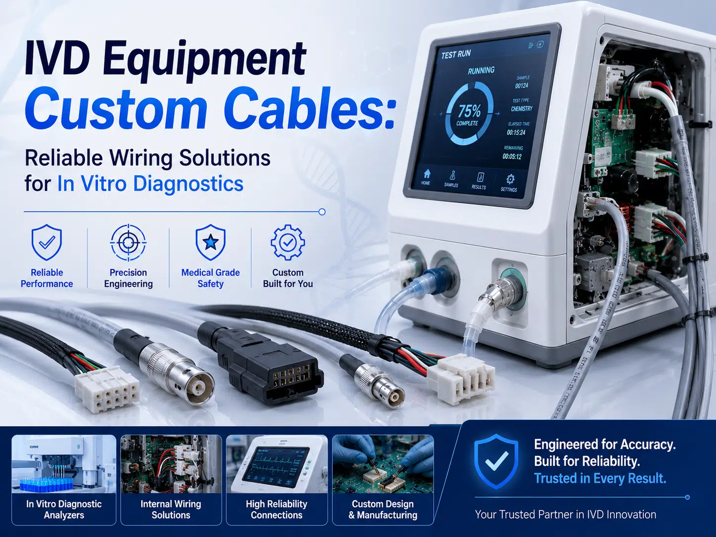
IVD equipment cable assemblies connect power supplies, heaters, pumps, motors, valves, sensors, optical modules, detectors, controllers, displays, networks, and service interfaces inside in vitro diagnostic instruments. The correct design depends on the specific analyzer, circuit, movement, electromagnetic environment, cleaning process, reagent exposure, risk controls, and regulatory market. There is no universal medical-cable voltage, shielding percentage, contact resistance, mating life, dielectric test, or temperature range that applies to every IVD instrument.
A custom cable assembly should be developed from the equipment architecture and controlled drawings, then verified in the production-intent instrument. The general difference between harnesses and cable assemblies is explained in the wire harness and cable assembly specification guide.
An IVD cable assembly is a defined combination of conductors, insulation, shielding, terminals, connectors, jackets, labels, branches, protection, and sometimes overmolded or sealed features. It may carry power, control, analog measurement, digital communication, motor feedback, heater current, optical-module signals, or safety-related interlocks.
Unlike a generic cable, an IVD assembly is tied to a particular instrument interface, mechanical layout, bill of materials, test method, and change-control process. The component relationships are summarized in the wire harness component guide.
| Instrument area | Typical connections | Primary design concerns |
|---|---|---|
| Power entry and distribution | Power supply, DC distribution, heaters, pumps, motors, fans, and protected branches | Current, voltage drop, insulation, circuit protection, temperature rise, separation, and service safety |
| Sample and reagent handling | Valves, pumps, liquid-level sensors, barcode readers, and fluidic modules | Reagent exposure, spills, cleaning, connector position, routing, and contamination control |
| Motion system | Motors, encoders, home sensors, locks, doors, and robotic axes | Flexing, bend radius, torsion, abrasion, dynamic length, strain relief, and fault detection |
| Detection and measurement | Optical detectors, electrodes, temperature sensors, pressure sensors, and analog front ends | Noise, leakage, shielding, grounding, pair geometry, connector cleanliness, and signal integrity |
| Control and data | Mainboards, distributed controllers, displays, Ethernet, USB, serial links, and internal buses | Protocol, topology, impedance, shielding, grounding, connector transitions, and EMC |
| User and service interfaces | Panels, switches, indicators, printers, scanners, diagnostics, and replaceable modules | Mating frequency, keying, labels, accessibility, service tools, and damage prevention |
Custom cable assemblies can be used in hematology analyzers, clinical chemistry analyzers, immunoassay systems, coagulation analyzers, molecular and PCR instruments, urinalysis systems, sample preparation devices, slide or cartridge handling equipment, and laboratory automation modules.
The cable requirements are determined by the actual equipment. A high-current heater branch, a photodetector connection, a moving pipetting axis, and a network cable should not share a single generic specification.
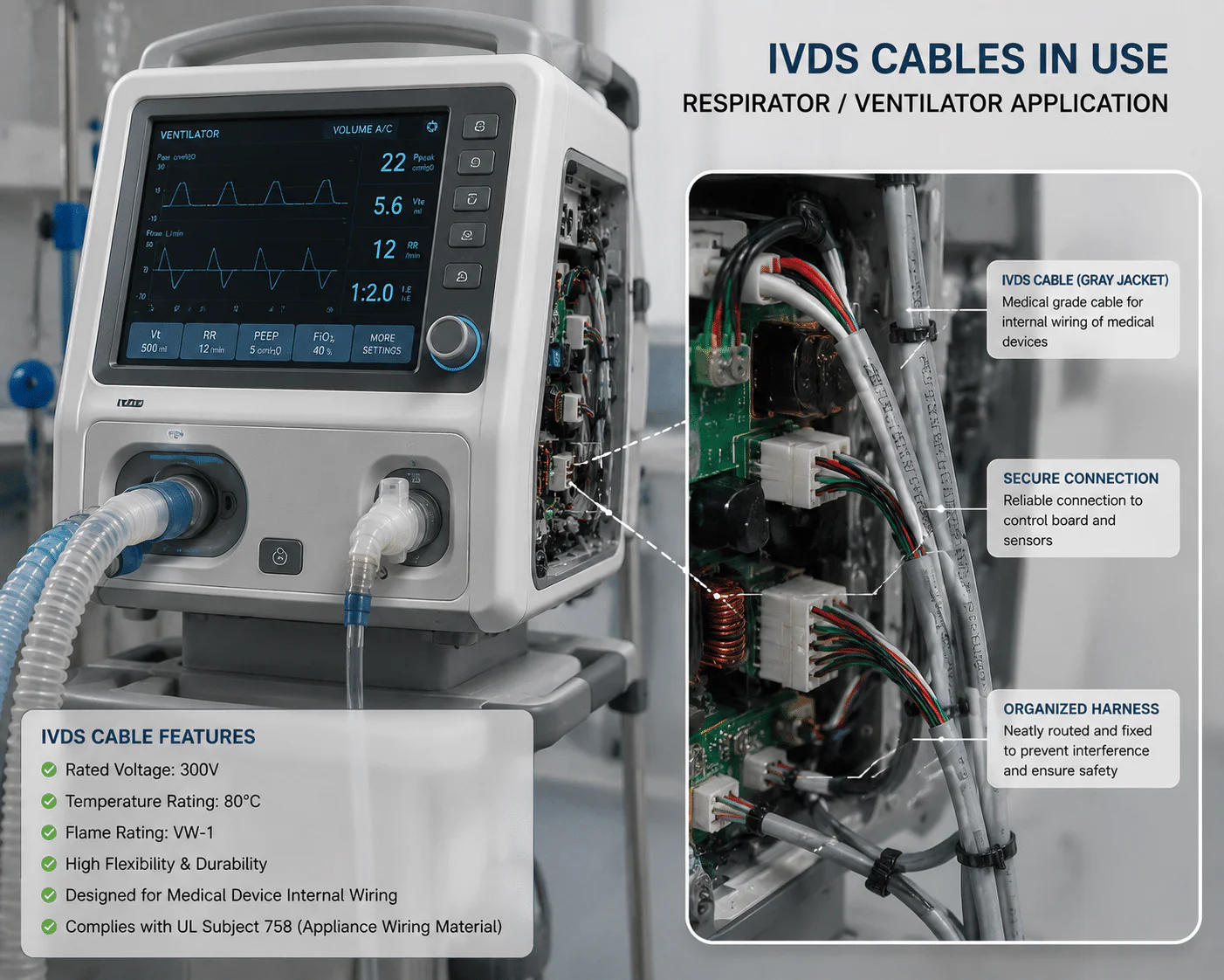
Define source voltage, normal current, inrush or stall current, duty cycle, branch protection, conductor length, connector temperature rise, allowable voltage drop, bundling, ambient temperature, and fault conditions. The relationship between current, conductor resistance, length, and connector loss must be evaluated across the complete current path.
The design workflow in the custom power cable guide provides a starting point. IVD equipment also needs clear separation between hazardous-energy or mains-related circuits, low-voltage power, sensitive measurements, communication, and protective earth according to the device safety architecture.
| Power design input | Why it matters | Evidence to retain |
|---|---|---|
| Operating and fault current | Controls conductor, terminal, connector, protection, and temperature rise | Circuit analysis, load profile, fuse or protection data, and test conditions |
| Voltage-drop limit | Affects motors, heaters, sensors, valves, and controller stability | Conductor and connector path, temperature, load, measurement points, and result |
| Loaded-cavity count | Multiple active contacts can change connector heating | Actual connector population and derating method |
| Duty cycle and airflow | Intermittent loads and enclosure cooling affect temperature | Instrument operating modes, ambient, mounting, and thermal test |
| Fault response | Defines protection and acceptable failure behavior | Risk control, protective device, wire and connector coordination, and verification |
Shielding should be selected from the source impedance, signal level, frequency, cable length, return path, coupling sources, connector transition, enclosure bonding, grounding scheme, and EMC plan. A braid or foil coverage percentage alone cannot guarantee measurement accuracy or compliance.
For higher-frequency and controlled-impedance paths, review the connector and transition principles in the RF cable assembly guide. Medical imaging has a different electromagnetic environment; the MRI RF harness guide should not be treated as a generic IVD specification.
Depending on the instrument, intended use, market, and manufacturer, standards such as IEC 61010-1, IEC 61010-2-101, IEC 61326-1, IEC 61326-2-6, ISO 14971, or quality-system requirements may be relevant. The exact edition, national adoption, product classification, risk-control role, test configuration, and acceptance criteria must be identified by the device manufacturer.
| Reference area | Possible document | What the cable supplier needs |
|---|---|---|
| Laboratory equipment safety | IEC 61010-1 and applicable particular requirements | Circuit classification, insulation, spacing, temperature, fire enclosure, wiring, protective earth, and test requirements |
| IVD equipment particular safety | IEC 61010-2-101 where applicable | Device-specific hazards, specimen and reagent areas, service conditions, and cable-related risk controls |
| EMC | IEC 61326-1 and IEC 61326-2-6 where applicable | Ports, cable lengths, shielding, grounding, test configuration, operating modes, and performance criteria |
| Risk management | ISO 14971 where applied by the device manufacturer | Cable-related hazards, failure modes, risk controls, verification, and change impact |
| Quality management | ISO 13485 or another applicable quality-system framework | Supplier controls, drawings, traceability, nonconformance, change notification, and records |
A standard reference does not mean WIRES is certified to that standard, and a cable assembly does not independently establish compliance of the complete IVD instrument.
Internal IVD cables may be exposed to detergents, disinfectants, blood or sample residue, buffers, acids, bases, solvents, dyes, oils, condensation, or other reagents. State the exact chemical, concentration, temperature, contact time, frequency, cleaning method, and acceptable change.
Cleaning, disinfection, and sterilization are different processes. Do not specify high-temperature sterilization for an internal instrument cable unless the actual device process requires it. Biocompatibility is relevant only when the final cable or material has the applicable patient, user, or sample-contact role defined by the device manufacturer.
| Material choice | Selection questions | Verification |
|---|---|---|
| PVC, TPE, TPU, silicone, fluoropolymer, or other insulation | Temperature, flexibility, chemicals, abrasion, diameter, flame, electrical rating, and processing | Exact material grade, data sheet, regulatory declaration, and finished-assembly testing |
| Connector housing and seals | Reagent, cleaning, temperature, mating, keying, locking, and service access | Manufacturer compatibility data and actual exposure testing |
| Overmold or strain relief | Flex transition, cleaning, pull, ingress, tooling, repairability, and dimensions | Material bond, geometry, flex and pull method, visual and dimensional inspection |
| Labels and markings | Cleaning, abrasion, readability, traceability, and replacement | Approved print, material, adhesion, exposure, and inspection criteria |
Robotic pipetting, sample transport, carousel movement, pump modules, drawers, doors, and service motion can repeatedly flex cables. A cable described as high-flex is not automatically suitable for the actual bend, torsion, acceleration, temperature, and routing.
Select connectors from the circuit, contact system, conductor and insulation range, keying, locking, mating frequency, service access, cleanliness, shielding, temperature, chemicals, voltage, current, and fault condition. Brand names alone do not prove suitability.
إن wire harness terminal guide covers material, plating, and crimp decisions. The connector selection guide explains why the terminal, housing, mating part, wire, and tooling must be treated as one system.
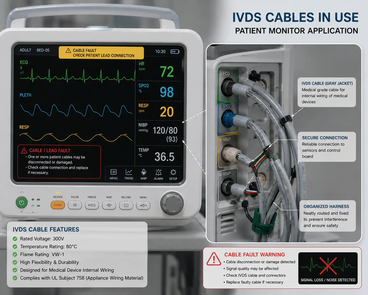
Tests should be selected from the device risk analysis and engineering requirements. A supplier should not apply one fixed hipot, insulation-resistance, pull-force, flex-cycle, or mating-cycle value to every IVD cable.
| Verification area | Variables to specify | Typical evidence |
|---|---|---|
| Pinout and continuity | Connector view, cavity map, polarity, shielding, shorts, opens, and test current | Approved drawing, fixture validation, test record, and traceability |
| Resistance or voltage drop | Load, measurement points, temperature, connector state, and acceptance limit | Results for the complete path and production-intent assembly |
| Dielectric and insulation | Circuit classification, voltage, waveform, duration, ramp, leakage, environment, and safety precautions | Method tied to the instrument insulation design and applicable standard |
| Signal integrity | Protocol, frequency, source and load, impedance, loss, crosstalk, jitter, or noise criteria | Bench and system-level measurements with the actual interfaces |
| EMC contribution | Cable length, routing, shield termination, enclosure, operating modes, ports, and performance criteria | Instrument-level emissions and immunity evidence |
| Flex and mechanical | Bend, torsion, travel, acceleration, cycles, load, temperature, and connector support | Electrical monitoring, visual inspection, conductor and shield condition |
| Chemical and cleaning | Exact reagent or cleaner, concentration, time, temperature, frequency, and method | Material, marking, seal, adhesion, dimensions, and electrical condition |
| Temperature | Operating, storage, current load, self-heating, cycling, dwell, and mounting | Electrical, mechanical, material, and connector results after exposure |
| Observed problem | Possible cable-related causes | Other causes to evaluate |
|---|---|---|
| Measurement drift or noise | Grounding, shield termination, routing, connector contamination, pair damage, or crosstalk | Sensor, optics, reagent, calibration, software, temperature, or power supply |
| Intermittent motion fault | Broken conductor, flex concentration, loose terminal, connector strain, or routing | Motor, encoder, controller, mechanism, obstruction, or software |
| Heater or motor underperformance | Voltage drop, high-resistance contact, undersized path, damaged conductor, or connector heating | Load, driver, protection, control, airflow, or mechanical resistance |
| Communication errors | Topology, impedance, shielding, connector transition, termination, power, or ground | Protocol, software, controller, network traffic, or device configuration |
| Chemical damage | Wrong jacket, seal, label, overmold, adhesive, or cleaning method | Unexpected spill, concentration, temperature, or maintenance practice |
| Failed safety or EMC test | Insulation, separation, routing, shield, bond, cable length, or connector choice | Complete instrument architecture, enclosure, PCB, filter, grounding, or test setup |
Review the industrial enclosure wiring guide for internal routing and separation principles. Then use the custom cable product range و custom development process to organize the project. A تجميع كابل النموذج الأولي should be evaluated in the intended analyzer before release. Production acceptance should follow a documented wire harness and cable quality plan.
If the analyzer includes a DVI display interconnect, see the medical and industrial DVI cable design guide for connector, link-mode, shielding, retention, and channel-validation considerations.
It is a documented cable or harness that connects power, sensors, motors, heaters, controllers, data interfaces, and other modules inside an in vitro diagnostic instrument.
No. Many laboratory and IVD instruments use the IEC 61010 family rather than IEC 60601-1, but applicability depends on the exact product, intended use, market, and regulatory strategy.
IEC 61326-1 and IEC 61326-2-6 may be relevant, depending on the instrument and market. The device manufacturer must define the edition, configuration, ports, performance criteria, and test plan.
No. Requirements depend on where the cable is used and whether it has patient, user, sample, reagent, or external contact. Material claims must be tied to the final device risk and regulatory requirements.
Only if the device process requires it. Many internal analyzer cables are cleaned or protected from spills rather than sterilized. Define the actual cleaning, disinfection, or sterilization method.
Use the circuit frequency, source and load, signal level, cable length, coupling sources, grounding, enclosure, connector transitions, and EMC plan. A fixed shielding percentage is not enough.
Before production release, evaluate it in the production-intent instrument for electrical function, motion, routing, EMC contribution, cleaning exposure, service access, and applicable safety risk controls.
IVD equipment cable assemblies should be specified from the instrument architecture, risk analysis, circuit requirements, mechanical motion, EMC design, materials, cleaning process, and regulatory strategy. Avoid universal cable ratings and use documented, device-specific verification.
For a project-specific review, send the instrument block diagram, interfaces, circuit and signal data, drawings, materials, movement, cleaning conditions, applicable standards, and acceptance requirements through the WIRES contact page.
 English English
 Vietnamese
 Indonesian
 Arabic
 Spanish


