Industrial AV cable assemblies carry audio, video, control, timing, or RF signals between equipment in environments where vibration, repeated motion, electromagnetic interference, fluids, temperature, and service access can affect performance. A reliable design starts with the interface specification and installation conditions, then defines the conductor geometry, impedance, shielding, grounding, connectors, jacket, strain relief, and validation plan as one system.
An industrial assembly is not simply a consumer cable with a stronger jacket. The signal path, mechanical construction, connector termination, and equipment grounding scheme must work together. This guide explains the decisions engineers and buyers should document before requesting a custom assembly.
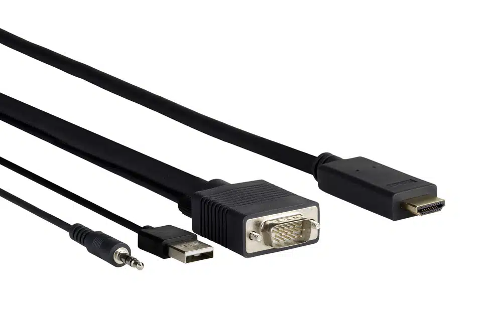
An industrial AV cable assembly is a finished interconnect built for a defined audio, video, RF, or mixed-signal application. It may include coaxial cables, shielded twisted pairs, discrete power conductors, control wires, fiber, drain wires, connectors, backshells, labels, branches, and protective sleeving. Unlike bulk cable, the assembly includes the terminated interfaces and the workmanship controls needed for installation.
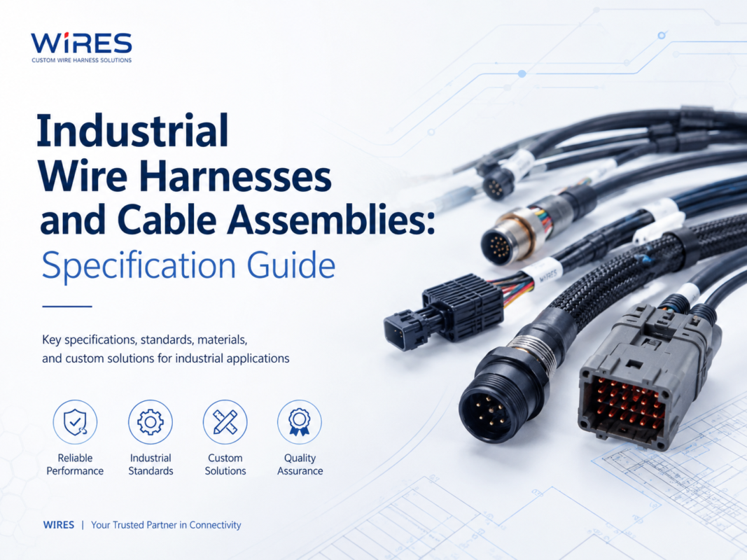
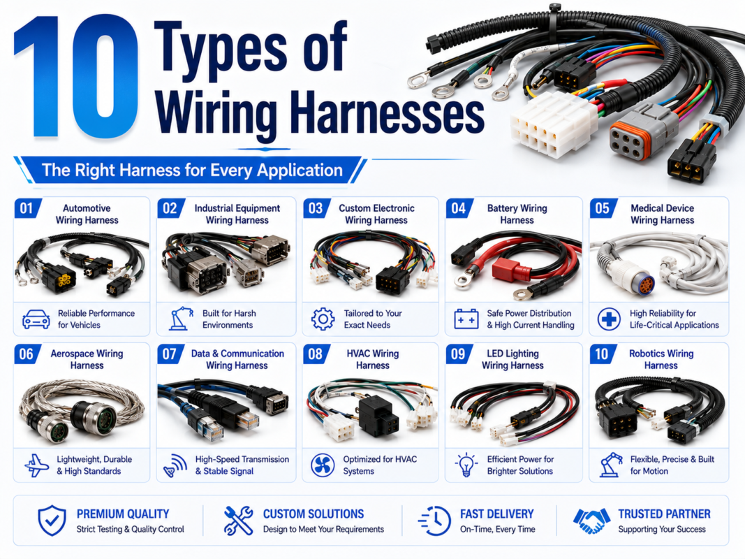
The correct construction depends on the application. A fixed camera link inside a cabinet, a moving machine-vision cable, a broadcast snake, and an RF test lead can all carry media signals, but they have different electrical and mechanical requirements. The broader wire harness and cable assembly specification guide explains when a bundled harness or a jacketed cable assembly is the better architecture.
Before selecting wire gauge, shielding, or jacket material, identify what each circuit carries and how the source and receiver are designed. Connector appearance alone does not define the protocol, pinout, impedance, or direction of a signal.
| Signal category | Typical design questions | Primary risks |
|---|---|---|
| Balanced analog audio | Source and load topology, pair twist, shield connection, channel count | Hum, induced noise, pinout errors, crosstalk |
| Unbalanced analog audio | Signal level, return path, cable length, equipment grounding | Ground-loop noise, capacitive loss, interference |
| Digital video or data | Protocol, lane count, differential impedance, bandwidth, equalization | Reflections, insertion loss, skew, intermittent link training |
| Coaxial video or RF | Required impedance, frequency range, connector series, return loss | Impedance discontinuity, shielding leakage, connector mismatch |
| Power plus AV | Voltage, current, startup load, separation, grounding, temperature rise | Noise coupling, overheating, voltage drop, unsafe pin sequencing |
| Control and communication | Protocol, termination, baud rate, topology, isolation | Reflections, common-mode noise, incorrect termination |
For studio, stage, and equipment-rack applications, a purpose-built mazo de cables may combine multiple labeled channels and connector types. For higher-frequency coaxial paths, review the separate RF cable assembly options before combining the RF path with power or control circuits.
Signal distance cannot be selected from a universal chart. Allowable length depends on the interface standard, data rate or frequency, cable construction, conductor size, dielectric, connector transitions, source amplitude, receiver margin, routing, and environmental temperature. Active repeaters, converters, or optical links may be more appropriate when a passive copper assembly cannot maintain the required margin.
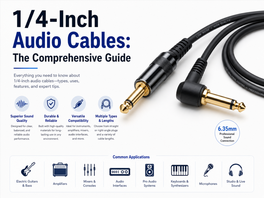
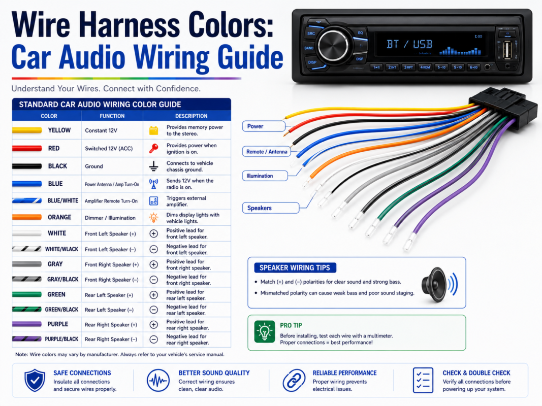
Balanced and unbalanced audio circuits require different wiring. A TRS connector may carry balanced mono audio, unbalanced stereo audio, an insert send/return, or a control function. The system schematic must define the actual contact assignment. See the 1/4-inch TS and TRS selection guide for common wiring functions and connector limitations.
Digital interfaces depend on controlled geometry. Pair twist, dielectric, conductor dimensions, shield placement, connector launch, and pair-to-pair skew all affect the channel. A cable that passes continuity testing can still fail at the target bandwidth. When a project uses DVI or a related differential video interface, the exact connector, link configuration, resolution, refresh rate, and equipment requirements should be recorded. The DVI cable design guide provides additional application questions.
Common systems may specify 50-ohm or 75-ohm components, but the required value must come from the interface or equipment specification. Mixing cable and connector impedances creates discontinuities. The drawing should identify the cable series, connector part numbers, frequency range, allowable insertion loss or return loss, and the test method used to confirm them.
Shielding performance depends on more than braid coverage. Foil, braid, spiral shields, combination shields, conduit, and connector shells behave differently across frequency and during motion. The termination method and the equipment grounding arrangement often determine whether the shield reduces interference or creates an unwanted current path.
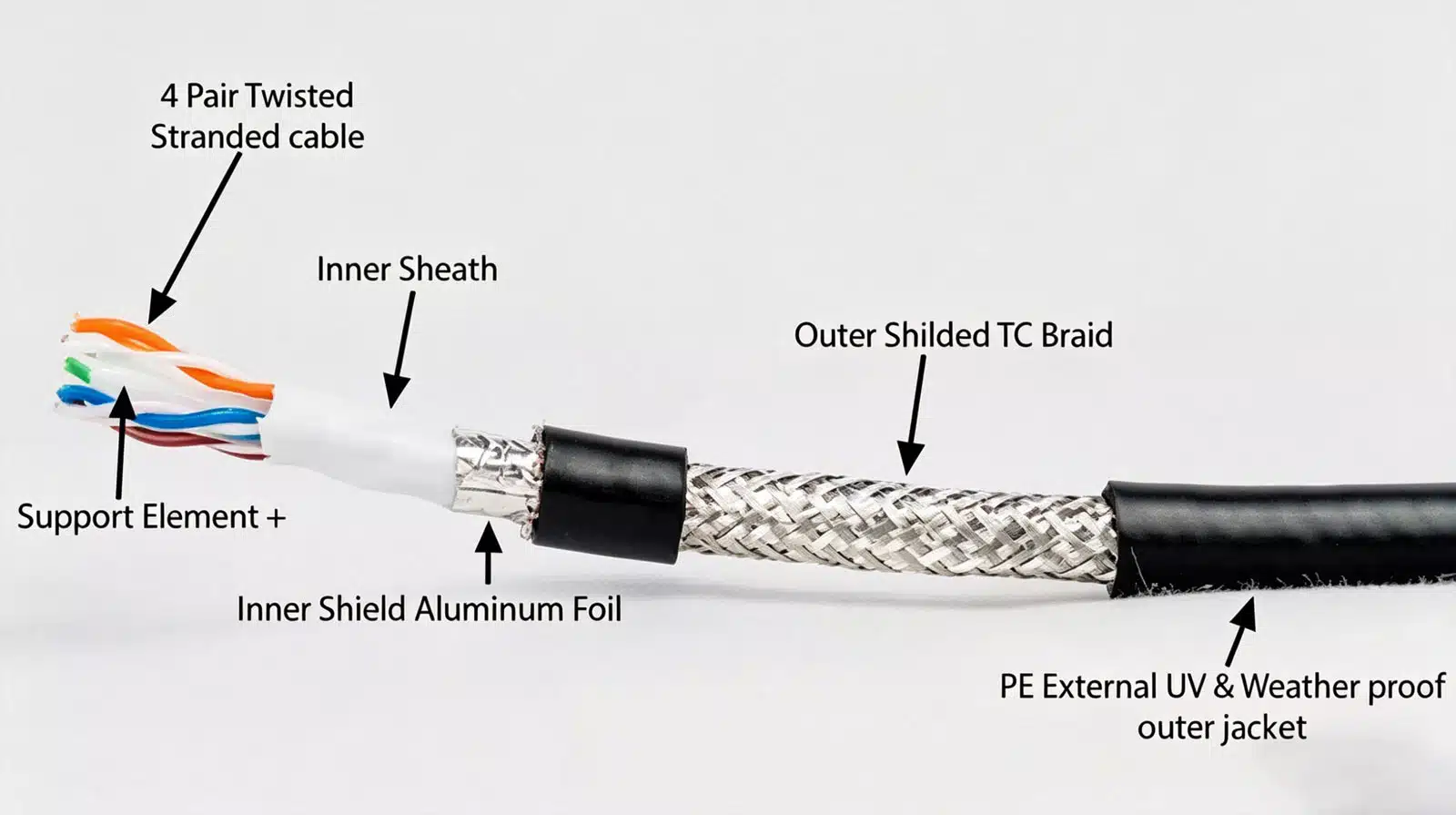
The design package should state whether each shield is connected at one end, both ends, through a capacitor or network, or according to an equipment-specific grounding plan. There is no universal rule that fits every frequency range and safety architecture. Grounding decisions should be reviewed with the equipment designer, especially near variable-frequency drives, servo motors, welders, high-current conductors, and sensitive measurement inputs.
A cable described as flexible is not automatically suitable for continuous flexing, torsion, robotics, or a cable carrier. Motion type, bend direction, minimum installed bend radius, travel distance, acceleration, torsion angle, cycle profile, temperature, and nearby fluids all influence construction and validation.
| Installation mode | Important inputs | Design focus |
|---|---|---|
| Fixed installation | Routing, clamps, service access, vibration | Strain relief, abrasion protection, connector support |
| Occasional flexing | Service movement, bend radius, handling frequency | Conductor strand design, jacket flexibility, bend control |
| Cable carrier | Travel, speed, acceleration, bend radius, fill | Layer geometry, torsion control, compatible jacket, guided routing |
| Robotic torsion | Rotation angle, axis, cycle profile, temperature | Torsion-rated construction and representative motion testing |
| Portable field use | Coiling, dragging, impacts, connector handling | Rugged jacket, visible labels, repairability, strain relief |
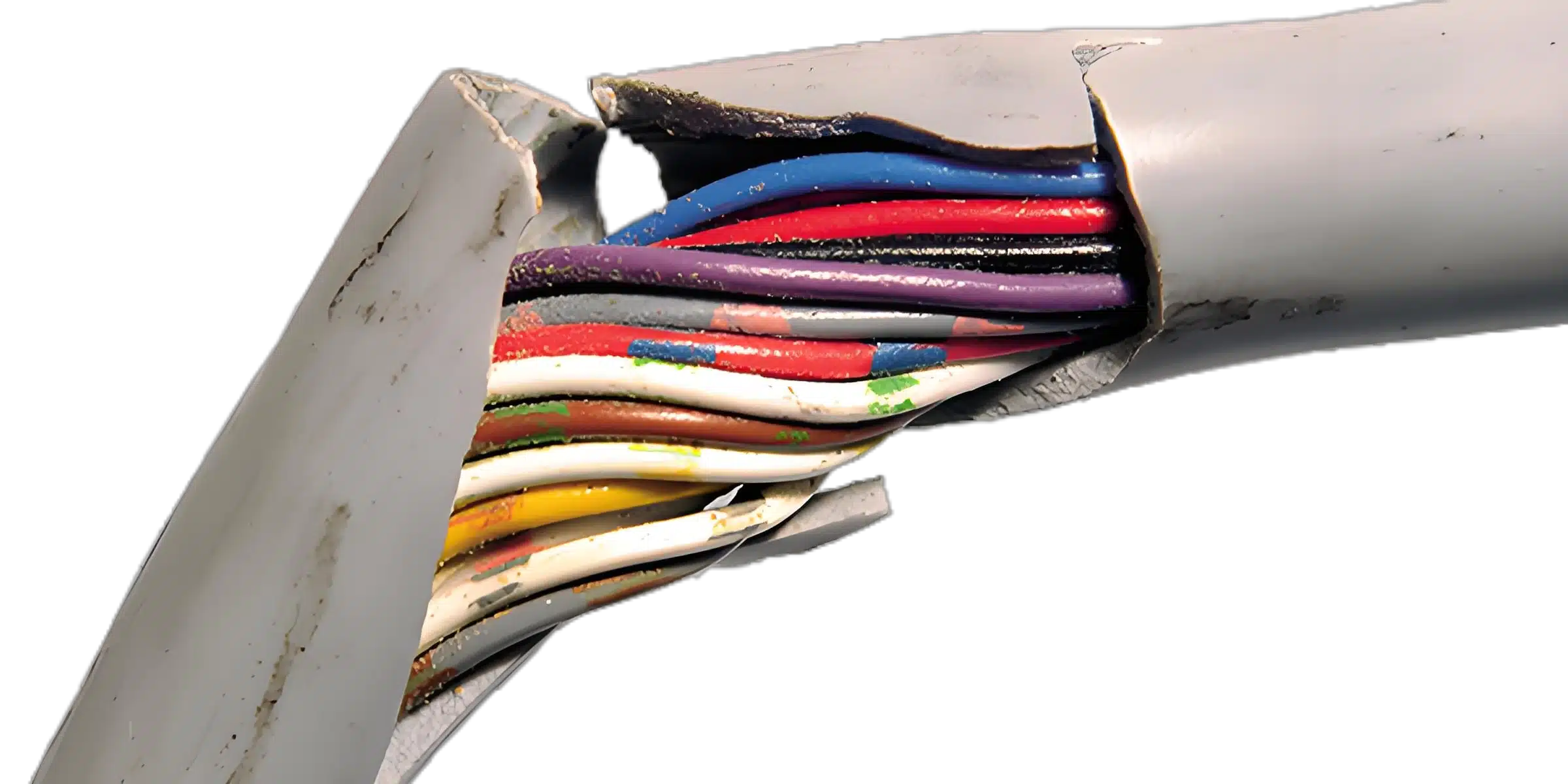
Flex-life figures are meaningful only when the sample, bend radius, load, speed, travel, temperature, failure criteria, and test equipment are stated. A result from one construction or test profile should not be presented as a guarantee for another installation.
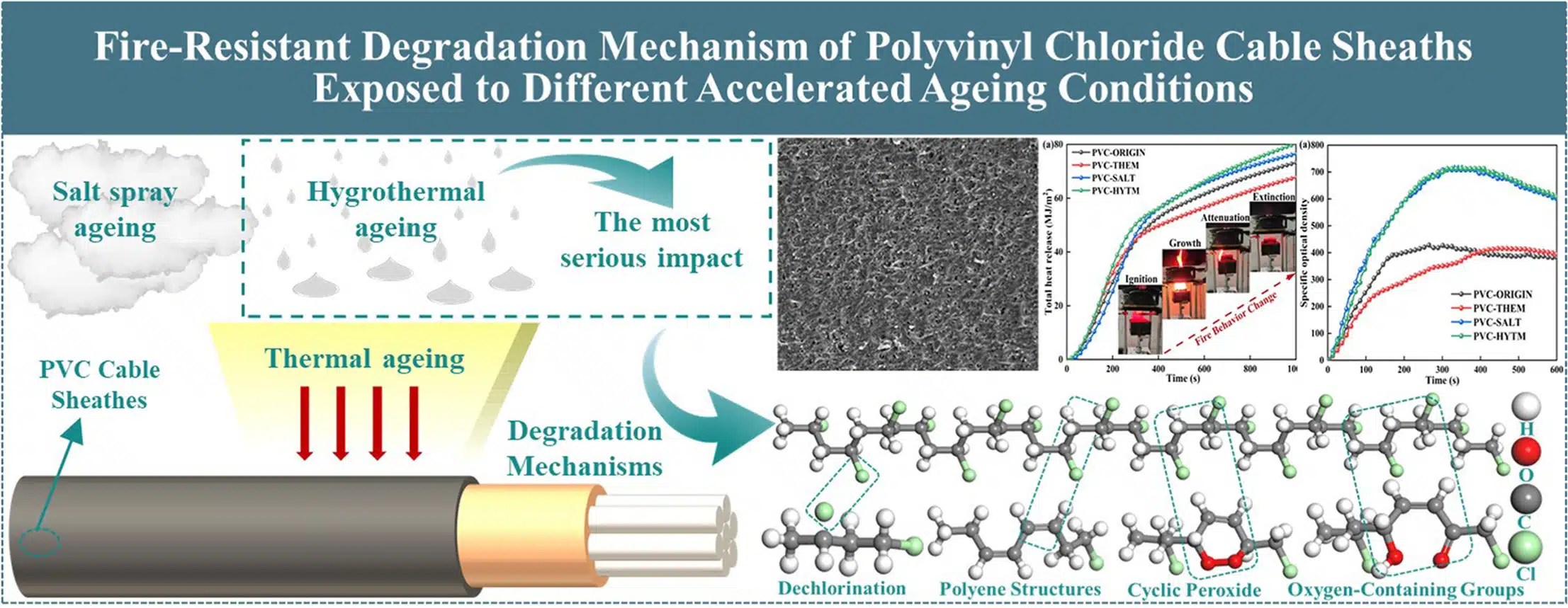
Jacket selection should be based on actual exposure rather than a generic label such as industrial grade or medical grade. Record the fluid name and concentration, cleaning method, contact time, temperature, UV exposure, abrasion, flame requirement, smoke requirement, installation code, and expected service handling.
| Environmental factor | Evidence to request |
|---|---|
| Oil, coolant, disinfectant, or cleaning chemical | Exact fluid compatibility data or a project-specific exposure test |
| Outdoor UV and weather | Material data and an applicable weathering method with stated duration and acceptance criteria |
| Low or high temperature | Operating and flexing limits for the complete cable, not only the base polymer |
| Flame, smoke, or halogen requirements | Exact standard, classification, installation jurisdiction, and third-party evidence where required |
| Washdown or ingress | Complete mated-connector system, sealing details, mounting condition, and applicable test plan |
| Abrasion or crushing | Routing protection, conduit or armor decision, and a representative mechanical test |
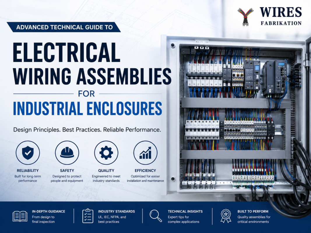
For cables installed inside an industrial cabinet, routing separation and protection should align with the complete control-panel design. The industrial enclosure wiring guide covers routing, labeling, grounding, terminals, and maintenance considerations. If power conductors share the assembly, the custom power cable guide explains current, voltage-drop, insulation, and connector inputs that must be documented separately from the AV signal path.
Connector selection should start with the mating interface and service environment. Specify manufacturer, series, exact part number, keying, gender, shell size, contact arrangement, plating option, backshell, seal, latch, mating-cycle expectation, mounting method, and approved equivalents. Similar-looking connectors are not necessarily interchangeable.
The pinout drawing should identify every signal, return, shield, drain wire, chassis connection, spare contact, and no-connect position. For mixed-signal assemblies, document separation and pin sequencing so power or high-current contacts do not compromise sensitive channels.
The connector and contact manufacturer normally defines the compatible wire range, strip length, tooling, contact insertion, and inspection criteria. Workmanship standards such as IPC/WHMA-A-620 may be referenced when required by the customer, but the contract should identify the revision, class, applicable sections, and any customer-specific acceptance criteria. A standards reference is not evidence that every product or supplier is certified.
Strain relief should transfer bending and pull loads away from conductor terminations without creating an abrupt stiffness transition. Options include clamp-style backshells, boots, heat-shrink transitions, potting, and overmolding. An overmolded cable assembly can improve sealing, handling, and repeatable geometry when the resin, cable jacket, connector, mold design, and adhesion are compatible. Ingress ratings must be validated for the complete mated system and specified test condition.
Multi-channel snakes and hybrid cables can reduce installation time and improve labeling, but they require careful channel mapping and mechanical balance. The number of channels should be chosen from the actual system architecture, not from a standard marketing configuration.
When a project combines several cable families, review the available custom interconnect product options and create a channel schedule before choosing the final bundle construction.
A useful request for quotation should give the supplier enough information to evaluate electrical performance, manufacturability, test coverage, and evidence requirements. At minimum, include the following:
| Specification area | Information to provide |
|---|---|
| Aplicación | Equipment, installation zone, function, market, and safety relevance |
| Signals | Protocol, analog or digital function, frequency or data rate, source and receiver details |
| Electrical limits | Impedance, insertion loss, return loss, resistance, voltage drop, skew, crosstalk, or other required limits |
| Mechanical layout | Overall length, tolerances, branch points, breakout lengths, bend radius, routing, and mounting |
| Conectores | Exact part numbers, pinout, keying, mating components, backshells, seals, and approved alternatives |
| Environment | Temperature, motion, vibration, fluids, UV, ingress, abrasion, cleaning, and installation rules |
| Materiales | Cable series or construction, jacket, shielding, sleeving, labels, and restricted substances |
| Validation | Qualification tests, acceptance tests, sample quantities, methods, limits, and report format |
| Production records | Drawing revision, bill of materials, inspection data, traceability, change control, and packaging |
En custom cable development process shows the typical path from requirements and drawing review through samples and production release. Requirements should be frozen by revision so changes to cable, connectors, tools, or test limits are controlled.
A prototype should answer specific engineering questions. It is not only a visual sample. Early builds can confirm connector fit, branch layout, installation reach, routing, flexibility, labeling, mating access, and basic electrical function. Performance tests should then represent the intended interface and environment.
A practical validation plan may include:
Use a conjunto de cables prototipo to resolve installation and performance risks before tools, molds, test fixtures, and production documentation are finalized.
Production controls should follow the risks identified in the drawing and validation plan. Appropriate controls may include material and part-number verification, calibrated tooling, crimp or solder process controls, contact retention checks, pinout testing, dimensional inspection, workmanship review, and lot traceability. The exact inspection and test coverage must be agreed for the project.
Electrical continuity alone does not confirm high-frequency performance, shield termination, contact retention, sealing, or long-term motion behavior. Likewise, a certification or quality-system claim does not replace product-specific evidence. Review the supplier’s wire harness quality approach, then request the records and acceptance data that matter for the assembly being purchased.
| Observed problem | Possible causes | Useful verification |
|---|---|---|
| Intermittent video or audio | Conductor fatigue, loose contact, connector movement, marginal channel loss | Wiggle test under operation, contact inspection, TDR or interface-specific test |
| Hum or background noise | Ground loop, shield termination, routing near power, unbalanced interface | Grounding review, route comparison, shield-current and signal measurement |
| Digital link drops | Excess loss, reflections, skew, poor connector transition, unsupported distance | Channel measurement, known-good equipment comparison, connector inspection |
| Crosstalk between channels | Insufficient separation, incorrect pair geometry, shared returns, shield errors | Channel mapping, near-end and far-end testing, construction review |
| Jacket cracking or swelling | Fluid incompatibility, UV, temperature, bend stress, cleaning process | Material identification, exposure history, representative compatibility test |
| Broken termination | Poor strain relief, handling load, unsupported connector, abrupt stiffness change | Sectioned sample, pull or bend test, installation and routing review |
| Ingress or corrosion | Seal damage, unmated exposure, capillary path, incompatible materials | Seal and mating inspection, fluid-path analysis, applicable ingress test |
Failure analysis should preserve the original assembly, mating connector, equipment state, logs, and installation evidence. Replacing the cable before documenting the condition can remove clues needed to distinguish a cable defect from an equipment, grounding, software, or installation problem.
Ask a prospective supplier to explain how it converts your system requirements into a controlled drawing, material list, process plan, and test plan. Useful evidence includes sample drawings, inspection formats, relevant equipment lists, traceability examples, and project-specific test reports with methods and limits. Avoid relying on broad claims such as zero loss, complete noise immunity, unlimited distance, or universal environmental resistance.
A qualified discussion should cover:
Provide the application, interface or protocol, signal frequency or data rate, cable length, connector part numbers, pinout, shielding and grounding requirements, motion profile, environment, drawing tolerances, test limits, quantity, and required records. Photos of the installation and mating equipment can help, but they should not replace a controlled drawing.
Sometimes a larger conductor reduces resistance or voltage drop, but it does not solve every signal-integrity limit. High-speed and RF links may be limited by dielectric loss, impedance, connector transitions, skew, reflections, equalization, and receiver margin. Length must be evaluated against the complete channel.
No. Shield material, geometry, frequency behavior, termination, grounding, flexibility, and connector shell design all matter. Additional shielding can increase size and stiffness without fixing an incorrect ground path or poor pair geometry.
That decision depends on the signal type, frequency range, equipment architecture, safety grounding, and electromagnetic environment. The equipment designer should define the shield connection and verify it in the installed system.
No. Overmolding is useful when the project needs controlled strain relief, sealing, handling durability, or compact geometry. Serviceable backshells, boots, clamps, potting, or heat-shrink transitions may be better for other applications.
Every assembly should be tested to the released project specification. Tests may include wiring, continuity, shorts, dimensions, workmanship, and interface-specific electrical measurements. Environmental and mechanical tests should use defined samples, methods, conditions, and acceptance criteria.
Yes, a hybrid assembly can combine these functions when separation, conductor sizing, shielding, grounding, connector contacts, heat, safety, and failure behavior are engineered together. The complete equipment architecture must define the limits.
To evaluate a custom project, send the current drawing, connector list, pinout, signal requirements, length and branch dimensions, installation photos, environmental conditions, motion profile, and test criteria. Contact WIRES for a project-specific review of industrial AV cable assembly requirements.
 English English
 Vietnamese
 Indonesian
 Arabic
 Spanish