



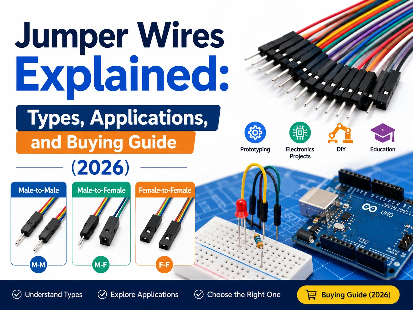
Jumper wires are short conductors used to make temporary or serviceable connections between breadboards, development boards, headers, sensors, and test points. Choose them by connector gender, pin pitch, terminal fit, wire construction, length, voltage and current requirements, routing, and expected handling. A jumper that works on a bench is not automatically suitable for a production product.
This jumper wire guide explains common types, applications, selection criteria, electrical limits, failure modes, and purchasing information for prototypes and low-volume equipment. For permanent assemblies, compare the architecture with the wire harness and cable assembly guide.
A jumper wire is an insulated conductor with a pin, socket, clip, or bare end used to bridge two circuit points. Jumper leads are common in electronics development because they allow a circuit to be assembled and changed without soldering every connection.
They can carry signals, reference grounds, and power only within the limits of the conductor, terminal, connector, source, load, ambient temperature, bundle, contact resistance, and duty cycle. The words low voltage do not establish a safe current rating.
| Part | الوظيفة | What to verify |
|---|---|---|
| قائد الفرقة الموسيقية | Carries current or signals | Material, strand construction, size, resistance, flexibility, and temperature rating |
| العزل | Separates and protects the conductor | Material, thickness, voltage, temperature, abrasion, chemicals, and stripping behavior |
| المحطة الطرفية | Creates electrical contact with a pin or socket | Exact series, plating, wire range, crimp geometry, and mating compatibility |
| الإسكان | Positions and protects terminals | Pitch, cavity count, polarization, latch, keying, and terminal retention |
| Strain transition | Limits loading at the termination | Expected bending, pulling, service access, and bend clearance |
A jumper lead forms an electrical path between two compatible points. On a solderless breadboard, a male pin enters a spring contact connected to other holes in the same internal row or rail. On a development board, a female socket mates with a pin header. The circuit still depends on correct pin mapping, common ground, compatible logic levels, power polarity, and suitable source and load limits.
Temporary connections are useful for exploration, but friction-fit contacts can loosen, oxidize, shift, or be inserted into the wrong location. Document the final prototype wiring before converting it into a PCB, cable assembly, or production harness.
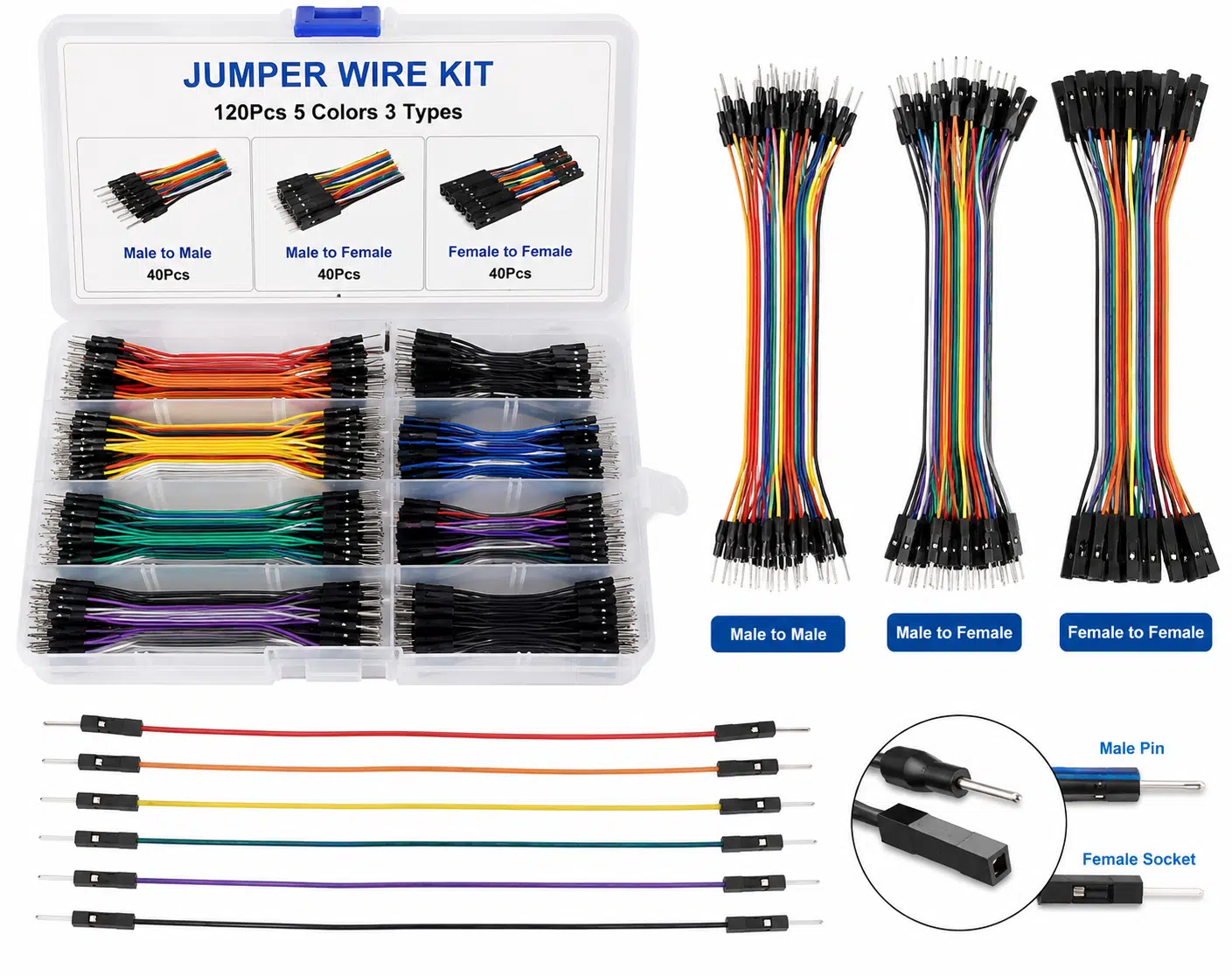
| النوع | Typical connection | Main checks |
|---|---|---|
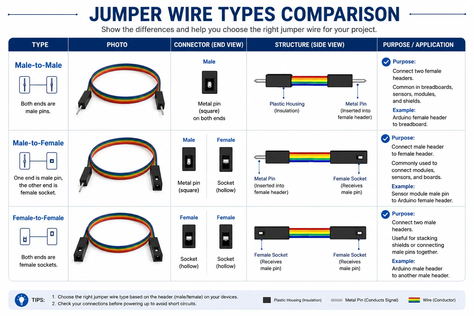
| Male-to-male | Breadboard to breadboard or female headers | Pin diameter, length, pitch, contact fit, and insulation clearance |
| Male-to-female | Breadboard to module or development-board header | Male pin fit, female socket series, polarity, and direction |
| Female-to-female | Pin header to pin header | Socket contact fit, housing pitch, retention, and adjacent-pin clearance |
| Preformed solid jumper | Short breadboard links | Conductor diameter, bend spacing, breadboard compatibility, and repeated-bend limits |
| Alligator-clip lead | Temporary test points, terminals, or larger conductors | Jaw contact, insulation, exposed metal, short-circuit risk, and rating |
| Custom multiway jumper harness | Fixtures, panels, test equipment, and low-volume devices | Connector series, pinout, branch lengths, labels, strain relief, and validation |
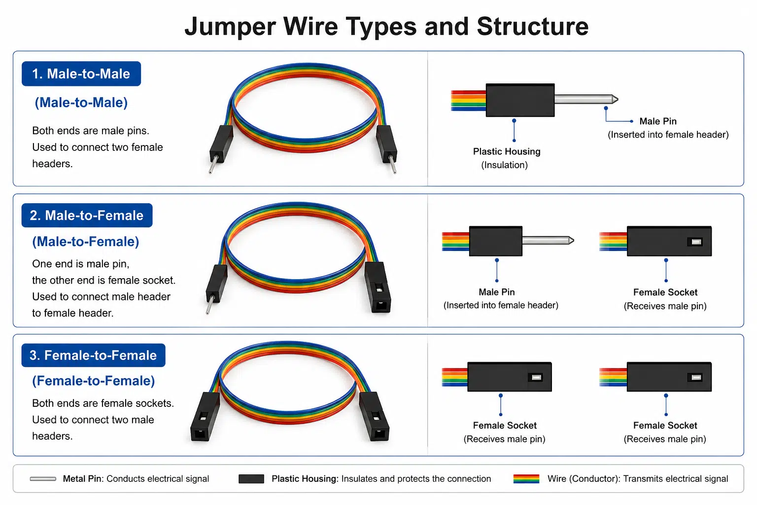
Male and female describe the contact interface, not the direction of current or signal. Many hobby breadboards and header systems use a nominal 2.54 mm pitch, but other pitches and proprietary terminal systems are common. Confirm the connector drawing and exact series instead of relying on the generic term DuPont-style.
The WIRES guides to أطراف توصيل مجموعة الأسلاك و terminals and connectors explain why a housing, terminal, wire range, crimp tool, and mating header must be treated as one compatible system.
Jumper wires connect power rails, microcontroller pins, sensors, displays, switches, and interface modules during circuit development. They are useful when the design changes frequently and soldering would slow each experiment.
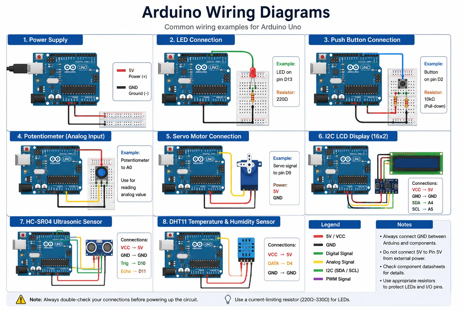
Color-coded jumpers can connect instruments, boards, and test points during development or troubleshooting. A test fixture should control pin mapping, contact life, operator access, strain, and replacement intervals. Loose bench leads are not a substitute for a released fixture design when measurement repeatability or safety matters.
Jumper kits make circuit relationships visible and easy to change. Training setups should include current limiting, correct power polarity, protected sources, clear labels, and supervision appropriate to the equipment.
Prototype leads may support sensors, controls, displays, and low-power lighting during development. Related design references include أحزمة الإضاءة و توصيلات أسلاك الإلكترونيات الاستهلاكية. Production use requires a separately approved connector, harness, and validation plan.
| الاتصال | Best use | المزايا | Limits |
|---|---|---|---|
| Loose jumper wires | Early prototypes and temporary tests | Fast changes and simple access | Low retention, routing errors, and inconsistent handling |
| Soldered point-to-point wiring | Repairs, experiments, and defined low-volume builds | Compact permanent joint when correctly designed | Harder to change; workmanship and strain relief are critical |
| Connectorized cable assembly | Serviceable products, fixtures, and equipment | Controlled pinout, retention, labeling, and replacement | Requires compatible components, tooling, drawings, and validation |
| Wire harness | Multi-branch production systems | Controlled routing, protection, identification, and assembly | Higher design and documentation effort |
Do not select a jumper by AWG alone. Safe current depends on conductor material and cross-section, strand construction, terminal rating, contact resistance, insulation temperature, ambient temperature, bundle size, ventilation, duty cycle, and allowable voltage drop. Use the most restrictive verified component limit and test the assembled path under defined conditions.
Copper and tinned-copper conductors are common, while PVC and silicone-based insulation are used in different products. No material is universally best. Select from documented flexibility, temperature, chemical, abrasion, flammability, diameter, stripping, and regulatory requirements. Do not infer performance from the words oxygen-free or premium.
A terminal crimp must match the terminal series, conductor, insulation diameter, strip length, tooling, and acceptance criteria. A terminal that slides onto a pin is not necessarily the correct mating contact. For a production-intent assembly, define retention, visual inspection, dimensional checks, and electrical tests in the drawing and control plan.
| العَرَض | Possible causes | Checks |
|---|---|---|
| Circuit works intermittently | Loose contact, worn breadboard, terminal backout, conductor break, or movement | Inspect each endpoint, substitute a verified lead, and reproduce movement under controlled conditions |
| Board resets under load | Voltage drop, weak source, thin conductor, high contact resistance, or poor ground | Measure at the load during operation and inspect the complete power and return path |
| Sensor readings are noisy | Long routing, poor ground, adjacent switching conductors, loose contact, or interface design | Shorten and organize the test path, verify grounding, and compare a controlled connection |
| Pin or socket becomes hot | Excess current, high contact resistance, poor crimp, damaged terminal, or partial mating | Disconnect safely, preserve the failed parts, and review load, contact, crimp, and rating evidence |
| Wrong function activates | Misplaced lead, mirrored connector view, incorrect color assumption, or undocumented change | Trace the pinout from approved face views and label both ends |
| Lead pulls out of housing | Wrong terminal, damaged retention lance, poor insertion, or excessive strain | Verify component series, seating, retention, routing, and strain relief |
WIRES can review a connectorized lead through its custom cable process and build a تجميع كابل النموذج الأولي before production release. Review the required wire harness quality controls; a continuity result alone does not prove current capacity, contact stability, signal integrity, or complete-product reliability.
They create temporary or serviceable electrical connections in breadboards, prototypes, development boards, test fixtures, education, and troubleshooting.
Male-to-male connects two compatible female contacts, while male-to-female connects a female receptacle or breadboard to a male header. Verify dimensions, pitch, and terminal series.
Yes, but only within the verified limits of the conductor, terminal, connector, source, load, duty cycle, temperature, bundle, and allowable voltage drop. Low voltage does not automatically mean high current is safe.
No. Nominal 2.54 mm pitch is common, but pin dimensions, housing geometry, terminal design, keying, and mating depth can differ. Check the exact components.
Loose hobby jumpers are primarily intended for prototypes and temporary work. A finished product should use an approved connectorized assembly or harness with documented ratings, retention, routing, workmanship, and validation.
Measure the installed path and allow only the service loop needed for access. Excess length can increase snagging, routing errors, resistance, and noise exposure.
Provide endpoint parts, connector drawings, pinout, gender, length, colors, wire and environment requirements, expected order range, and inspection and test criteria.
For a custom prototype lead, fixture cable, or low-volume connectorized assembly, send the device information, connector photos, part numbers, pinout, length, electrical load, routing, and validation plan. Contact WIRES to review the assembly before production.
 English English
 Vietnamese
 Indonesian
 Arabic
 Spanish


