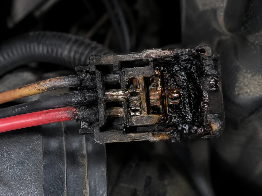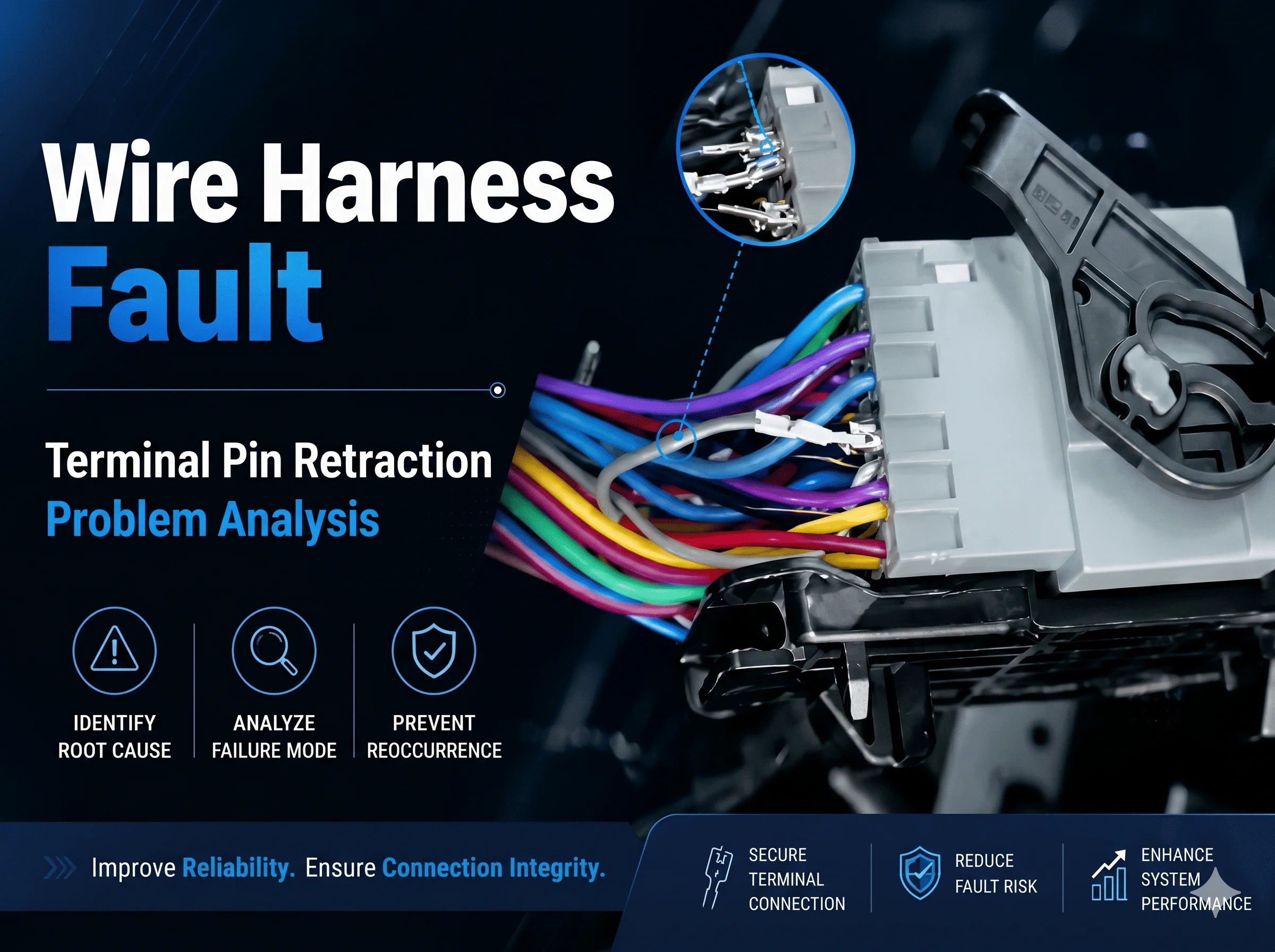
Terminal pin retraction, also called terminal backout or push-back, occurs when a terminal does not remain in its specified position inside a connector housing. It can be caused by incomplete insertion, a damaged retention lance, an open secondary lock, terminal deformation, wrong part selection, seal interference, mating misalignment, test-fixture contact, or harness strain. Prevention requires control of the complete terminal, housing, wire, seal, crimp, insertion, lock, test, and mating process.
This article focuses specifically on terminal position and retention. For the wider set of contact, sealing, heat, corrosion, and housing problems, see the automotive connector failure guide.
A correctly assembled terminal reaches its final cavity position, engages the primary retention feature, remains compatible with the seal and secondary lock, and mates with the opposing contact without being displaced. Retraction exists when the terminal moves behind the required position before, during, or after mating.
| Related term | المعنى | Typical evidence |
|---|---|---|
| Incomplete insertion | The terminal never reached the final seated position | Terminal face is recessed, primary lock is not engaged, or secondary lock cannot close correctly |
| Terminal backout | A seated or apparently seated terminal moves rearward in the housing | Terminal position changes during handling, testing, mating, vibration, or wire loading |
| Pin push-back | The mating contact pushes the terminal rearward during connector engagement | Misalignment, bent contact, low retention, or housing damage appears after mating |
| Terminal pullout | Wire force removes the terminal from the cavity | Damaged retention feature, excessive harness tension, or incorrect repair |
| Contact disengagement | The contacts do not achieve or maintain the required overlap | Open circuit, intermittent signal, or excessive voltage drop under the relevant condition |
Terminal backout is not the same as a poor crimp, although crimp deformation can prevent full insertion or transfer force into the locking feature. Review the wire harness terminal guide for material, plating, crimp, and selection fundamentals.
A terminal must match the housing cavity, mating interface, conductor size, insulation diameter, seal range, plating system, and application. A physically similar terminal can have a different locking geometry, contact position, crimp range, or material thickness.
Connector families must be treated as systems. The same principle is explained in the connector type and selection guide: terminal, housing, mating part, wire, and tooling are not independent substitutions.
The terminal retention lance, housing shoulder, cavity wall, or another primary-locking feature can be bent, flattened, cracked, worn, contaminated, or dimensionally incorrect. Damage may occur during crimping, handling, insertion, removal, rework, or unauthorized probing.
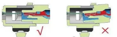
Common contributors include wrong orientation, inadequate insertion travel, an obstructed cavity, seal drag, deformed terminal, excessive wire bend, poor operator access, and failure to confirm the final position. A click can be useful feedback on some designs, but sound alone is not proof of correct seating.
Terminal position assurance or other secondary-lock features may be left open, forced closed over an unseated terminal, damaged, or installed in the wrong sequence. The secondary lock supplements the primary retention system; it does not repair a damaged terminal or cavity.
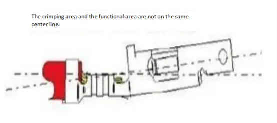
Incorrect applicator setup, terminal support, feed, wire position, strip length, crimp height, press condition, handling, or cutting can bow, twist, roll, or flatten the terminal. Even small deformation can increase insertion force, prevent the lock from engaging, or misalign the mating interface.
A wire seal that is wrong for the insulation diameter, damaged, folded, dry, contaminated, or incorrectly positioned can create insertion resistance or push the terminal rearward. Excessive wire stiffness, a tight rear bend, or an oversized insulation crimp can produce the same effect.
Bent male contacts, damaged keys, tilted engagement, foreign material, incomplete connector alignment, or forcing the wrong mating pair can push a terminal backward. Both halves must be inspected because the source of the displacement may be on the device side.
Tight routing, insufficient slack, branch direction, connector orientation, unsupported harness mass, engine movement, body flex, vibration, and service pulling can load individual wires. The connector retention feature should not carry continuous harness tension.
Unprotected terminals, exposed connector faces, stacked assemblies, unsuitable trays, tangled branches, and contact with tools or fixtures can bend terminals or damage locks before final assembly.
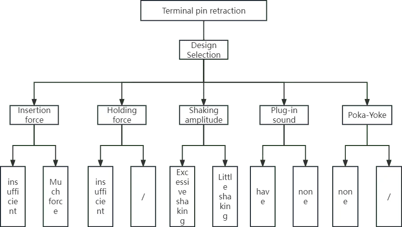
| Factor | Why it matters | How to control it |
|---|---|---|
| Insertion force | Excess force can indicate interference, deformation, seal drag, or a wrong part; unusually low force can indicate missing engagement | Use the connector-specific method, sample condition, and acceptance limits |
| Primary retention | Holds the terminal at the specified cavity position | Verify terminal and housing geometry, material condition, insertion, and approved retention test |
| Secondary lock | Adds position assurance and can help identify incomplete insertion | Control sequence, final position, damage, and part revision |
| Terminal position | Determines contact overlap and mating alignment | Use visual standards, cavity references, gauges, or vision checks where appropriate |
| Seal and insulation fit | Can support sealing or create rearward force and insertion resistance | Match insulation diameter, seal range, lubrication, and assembly instructions |
| Wire exit geometry | Side load can work the terminal out of position | Control branch direction, bend, clip location, slack, and strain relief |
| Mating interface | Misalignment can push a terminal back | Inspect keys, guides, contact straightness, latches, and connector alignment |
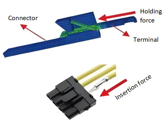
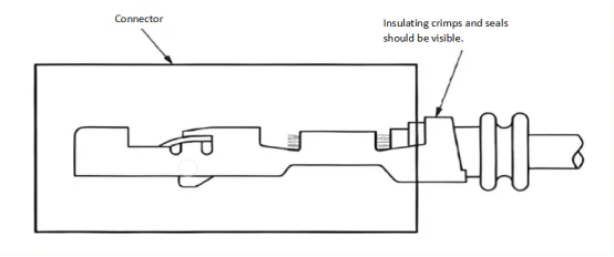
Compare the terminal face, rear wire position, seal position, primary lock, and secondary lock with the approved connector drawing or visual standard. Use the correct viewing angle and lighting; a terminal can appear seated from the rear while remaining recessed at the mating face.
Confirm that the secondary lock reaches its specified final position without excessive force. If it will not close, do not force it. Find the unseated terminal, wrong part, interference, or damaged feature.
Some processes use a controlled wire pull, push, or terminal-position method. The force, direction, duration, sample plan, fixture, and acceptance criteria must come from the connector or customer specification. An arbitrary tug can damage a good crimp, seal, terminal, or housing.
Gauges, camera systems, profile checks, or connector-specific fixtures may verify terminal depth. The method must reference a stable housing datum and account for connector tolerance.
Continuity and circuit tests are valuable but do not automatically prove terminal retention. A test probe can temporarily push an unseated terminal forward, create contact, and allow a defective assembly to pass. Fixture design must limit damaging travel and avoid masking the defect.
When specified, inspect connector alignment, mating force, latch engagement, contact position after mating, and the condition of both halves. Do not use repeated mating as an improvised test if the connector has a controlled service-cycle requirement.
| Test risk | How it hides the defect | التحكم |
|---|---|---|
| Probe pushes terminal forward | Electrical contact exists only while the fixture is connected | Use connector-specific probe geometry, travel stops, and terminal-position inspection |
| Probe is misaligned | It contacts the housing, spreads the terminal, or enters beside the contact | Add alignment guides and maintain fixture condition |
| Low test current | Continuity passes despite resistance that matters under operating load | Use the approved circuit test and acceptance criteria |
| Worn fixture contact | Creates unstable results or physical damage | Define inspection, cleaning, life control, and replacement |
| No post-test position check | Fixture-induced movement is not detected | Inspect terminal position after testing where risk requires it |

Use the documentation structure in the wire harness and cable assembly specification guide to keep connector requirements tied to the complete assembly.
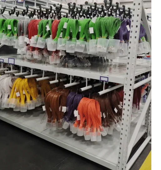
Use trays, caps, covers, separators, defined branch placement, and controlled work-in-process packaging where the risk requires them. Protection should prevent terminal impact, connector-face contamination, seal damage, and harness tangling without adding new stress.
Audio feedback, operator feel, or a single rear-view check can support the process but should not be the only acceptance method.
Use probes and guides compatible with the terminal system. Define probe diameter, shape, travel, alignment, contact force, maintenance, replacement, and fixture verification. The fixture must detect circuit faults without spreading contacts or pushing terminals into a temporary passing position.
Route the harness so branches do not pull terminals rearward. Align the connector before mating, engage it along the designed direction, and confirm latch or connector-position-assurance features. The automotive harness design guide explains routing, protection, and vehicle-zone considerations.
USCAR-2, USCAR-21, IEC 60352-2, OEM specifications, and connector-manufacturer documents may be relevant to terminal retention, crimped connections, and connector performance. The applicable document, revision, class or performance level, specimen preparation, wire and terminal combination, test sequence, and limits must be stated. A standards reference is not a WIRES certification claim.
Programs with harsh-environment or traceability requirements may need additional controls like those discussed in the military cable assembly guide.
| Finding | Possible root cause | Evidence to collect |
|---|---|---|
| Terminal never reached final position | Wrong orientation, interference, seal drag, deformation, obstructed cavity, or incomplete work | Insertion record, terminal profile, cavity condition, seal and wire combination, visual standard |
| Terminal moves after handling | Primary lock damage, wrong terminal, housing damage, wire strain, or inadequate retention | Part identity, retention feature condition, approved retention result, routing and packaging |
| Terminal moves during mating | Bent mating contact, misalignment, key damage, wrong pair, or incomplete lock | Both connector halves, mating marks, contact straightness, keying, latch and secondary lock |
| Electrical test passes but vehicle test fails | Probe temporarily repositions terminal, insufficient test condition, harness movement, or mating displacement | Probe travel, fixture alignment, post-test position, load condition, and final mating evidence |
| Repeated failure in one cavity | Cavity damage, mold dimension, local routing load, part variation, or device-side interference | Housing measurement, cavity comparison, mating device, branch direction, lot and tooling data |
Follow the customer, connector-manufacturer, or OEM repair instruction. Do not glue a loose terminal in place, bend retention features without an approved method, or reuse a terminal whose lock, plating, contact, or crimp has been damaged.
Repair decisions should consider the housing cavity, terminal, seal, conductor, wire length, mating half, fluid ingress, heat damage, circuit safety relevance, and available service parts. After repair, repeat the specified retention, position, electrical, sealing, and functional checks.
Review the available custom wire harness products و custom development process when preparing requirements. A تجميع كابل النموذج الأولي can be checked for insertion, retention, fixture interaction, routing, and final mating before release. Production controls should follow a documented wire harness quality plan.
Common causes include incomplete insertion, damaged retention features, an open secondary lock, wrong parts, terminal deformation, seal interference, mating misalignment, harness strain, and test-fixture contact.
Not always. Some connector systems provide useful audible or tactile feedback, but the sound can be weak, confused with another feature, or produced before final seating. Use the approved position and lock checks.
It may detect an open circuit, but it can also miss the defect if a probe pushes the terminal forward or if the problem appears only during mating, vibration, or load. Electrical testing should be combined with position and retention controls.
No. Retention methods and limits depend on the connector system, terminal, wire, housing, direction, fixture, and specification. An arbitrary pull can damage a good assembly.
Only if the approved repair procedure permits it and the terminal, lock, housing, seal, conductor, and contact remain acceptable. Repositioning does not correct a damaged retention feature.
Crimping can bend, twist, bow, or otherwise deform the terminal, increase insertion force, damage the lock, or create wire geometry that pulls the terminal rearward.
Connector-manufacturer, customer, OEM, USCAR, IEC, and other documents may apply. State the exact document, revision, part combination, method, and limits rather than using a universal value.
Terminal pin retraction prevention depends on a controlled system: correct parts, straight and compliant terminals, complete insertion, functional primary and secondary locks, compatible seals and wires, protected handling, non-damaging electrical fixtures, low-strain routing, and aligned final mating.
For a project-specific review, send the connector system, cavity map, terminal and wire data, crimp requirements, failure samples, fixture design, routing, and acceptance criteria through the WIRES contact page.
 English English
 Vietnamese
 Indonesian
 Arabic
 Spanish