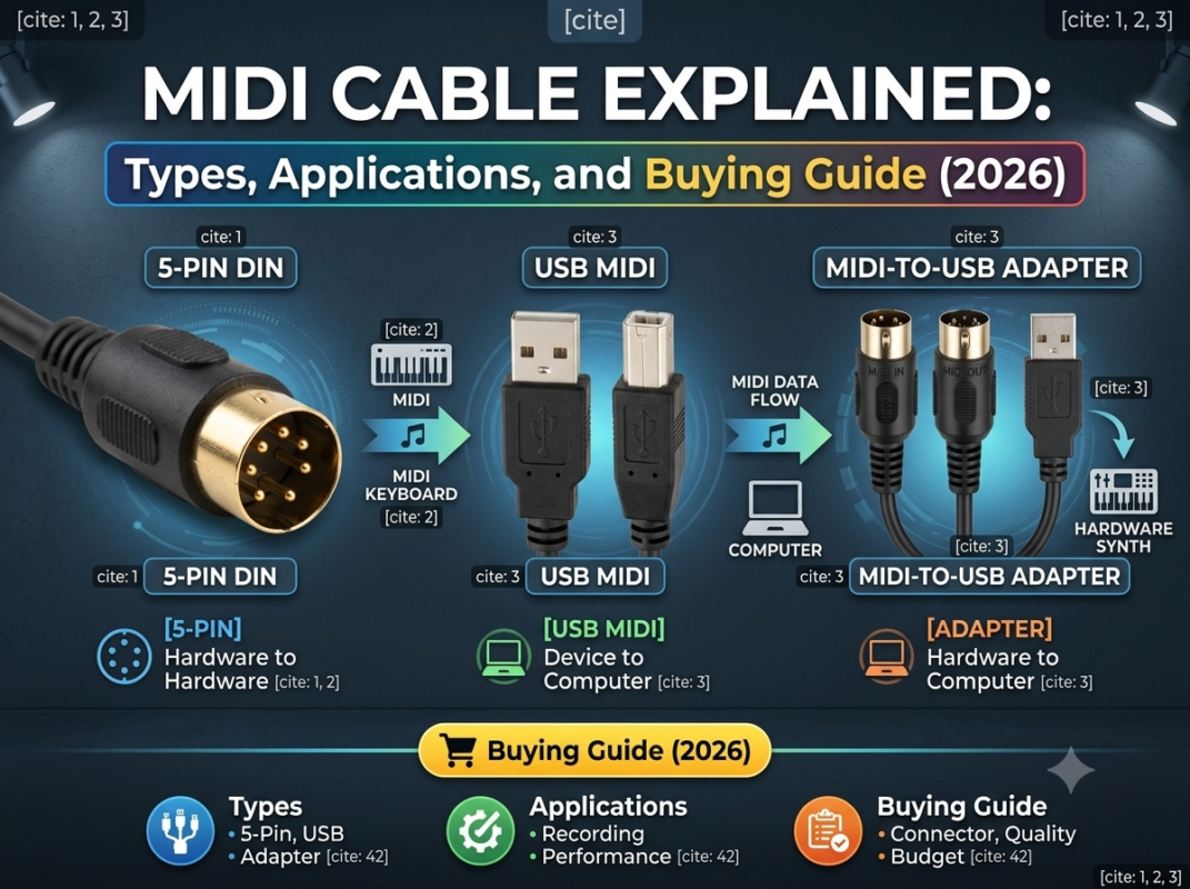
A custom MIDI cable must match the physical connector, MIDI transport, pin assignment, signal direction, cable length, routing environment, and connected equipment. A 5-pin DIN lead can be passive, but a USB-MIDI connection requires active interface electronics, and a 3.5 mm TRS MIDI connection must use the correct Type A or Type B mapping. Connector fit alone does not prove compatibility.
This guide focuses on specifying and validating custom MIDI cable assemblies for instruments, controllers, stage systems, studios, service equipment, and integrated products. For a broad introduction to MIDI cable types and applications, read the separate MIDI cable buying guide.
MIDI, or Musical Instrument Digital Interface, carries performance and control messages such as note events, velocity, controller changes, program changes, timing, and system data. It does not carry the analog audio produced by a synthesizer, mixer, or instrument.
A custom MIDI cable adapts the physical assembly to a defined system. Customization may include connector combinations, pin mapping, direction labels, right-angle exits, overmolding, jacket material, finished length, shielding termination, breakout branches, panel connections, identification, packaging, and project-specific tests.
| System layer | What it defines | Why it matters to cable selection |
|---|---|---|
| Message and protocol | MIDI messages, channels, timing, and device behavior | A cable cannot add a message type or function that the devices do not support |
| Transport | DIN MIDI, USB-MIDI, TRS MIDI, network MIDI, or a proprietary implementation | Different transports may require active electronics, drivers, or configuration |
| Electrical interface | Current-loop, USB signaling, or another specified circuit | Pin-to-pin continuity alone may not prove compatibility |
| Connector and pinout | DIN, TRS, USB, panel connector, or custom breakout | Similar-looking connectors can use different mappings and directions |
| Mechanical installation | Length, routing, strain relief, flexing, pull load, and service access | The assembly must fit and remain stable in the intended environment |
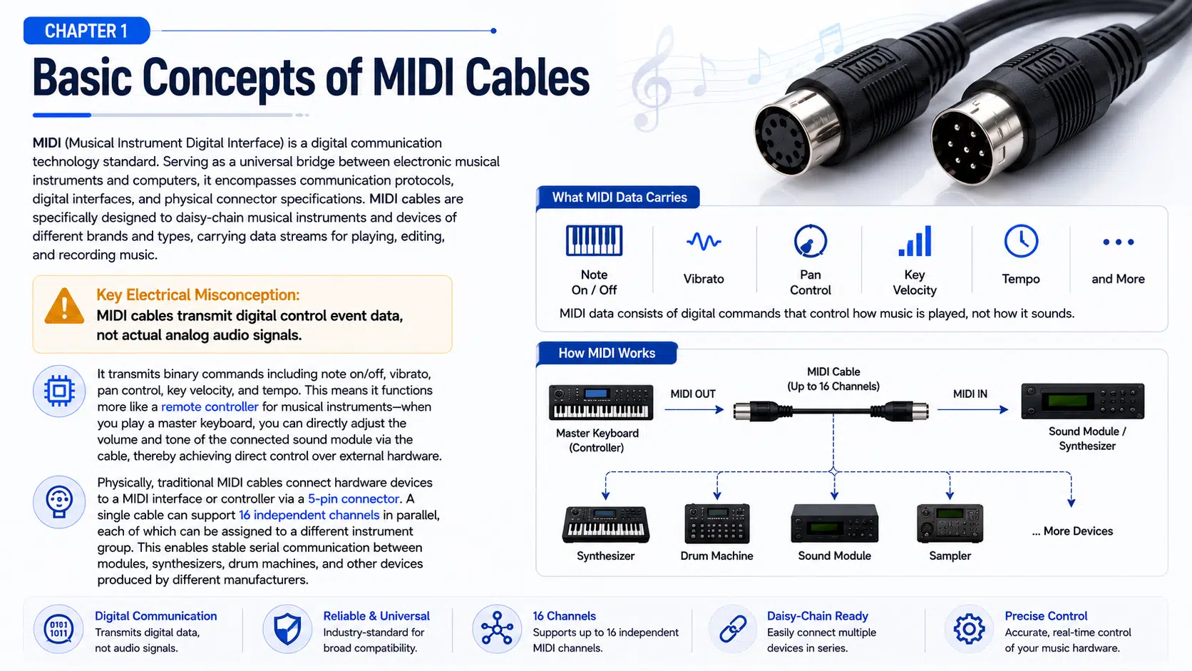
Traditional MIDI 1.0 DIN communication uses an asynchronous serial data stream at 31.25 kbit/s. One MIDI 1.0 port can address 16 logical channels, but channels are message identifiers rather than sixteen separate conductors in the cable. The connected devices determine which messages and channels they transmit or respond to.
The familiar connector is a 5-pin DIN shell. In the traditional MIDI data connection, only the contacts assigned by the applicable MIDI electrical specification are used for the data circuit and shield arrangement. Do not repurpose unused-looking pins without a documented device design, because some equipment and nonstandard accessories may use connectors differently.
The receiving circuit is designed around electrical isolation in a compliant MIDI implementation. Cable shielding, connector termination, grounding, device design, and installation all influence noise behavior. A cable alone cannot guarantee the EMC performance of the complete system.
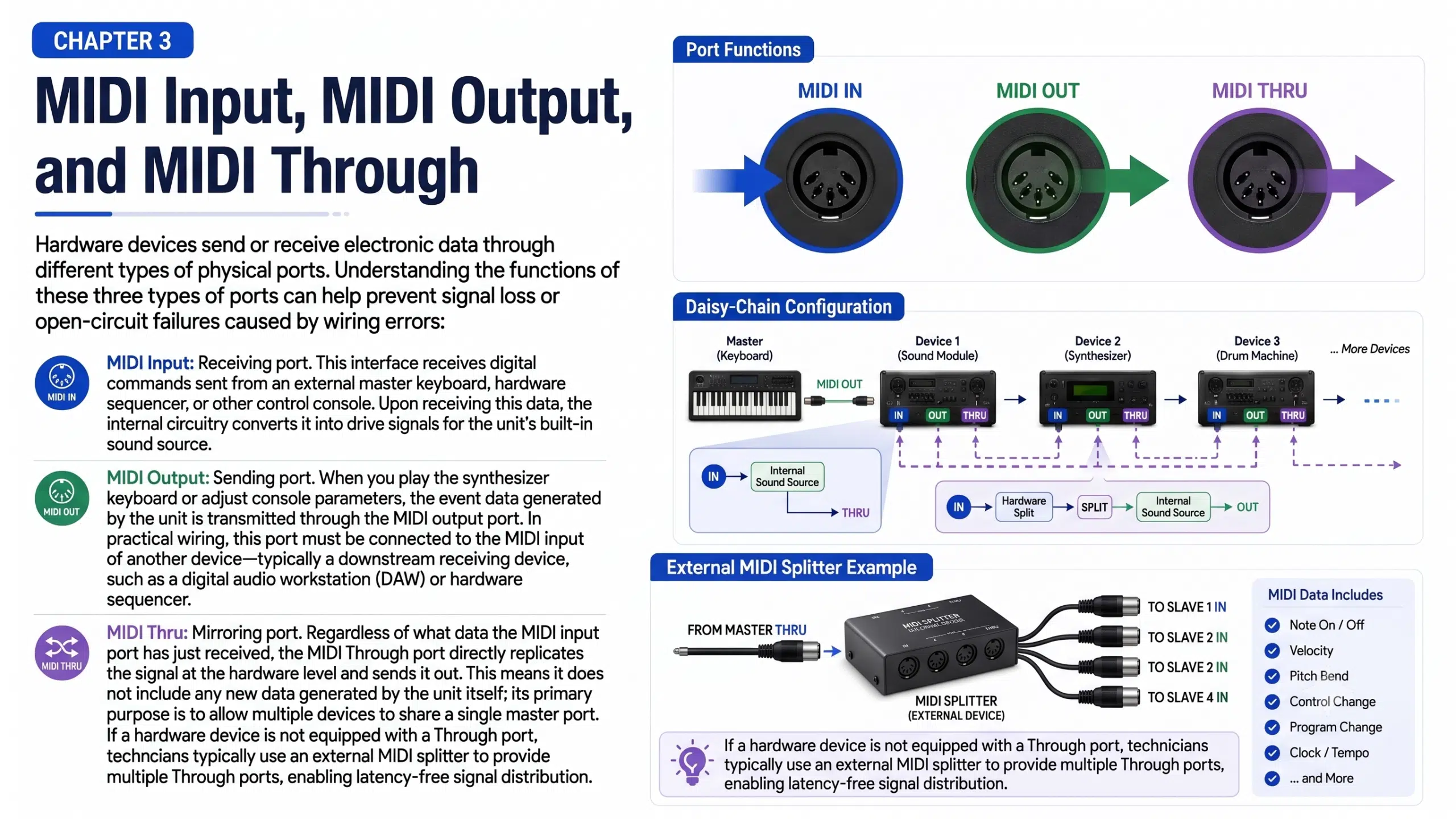
| Port | Function | Connection rule |
|---|---|---|
| MIDI Out | Sends messages generated or routed by the device | Connect to the receiving device’s MIDI In |
| MIDI In | Receives messages from another device | Connect from the sending device’s MIDI Out or Thru |
| MIDI Thru | Forwards data received at MIDI In, depending on device design | Connect to the next device’s MIDI In when the topology and timing are acceptable |
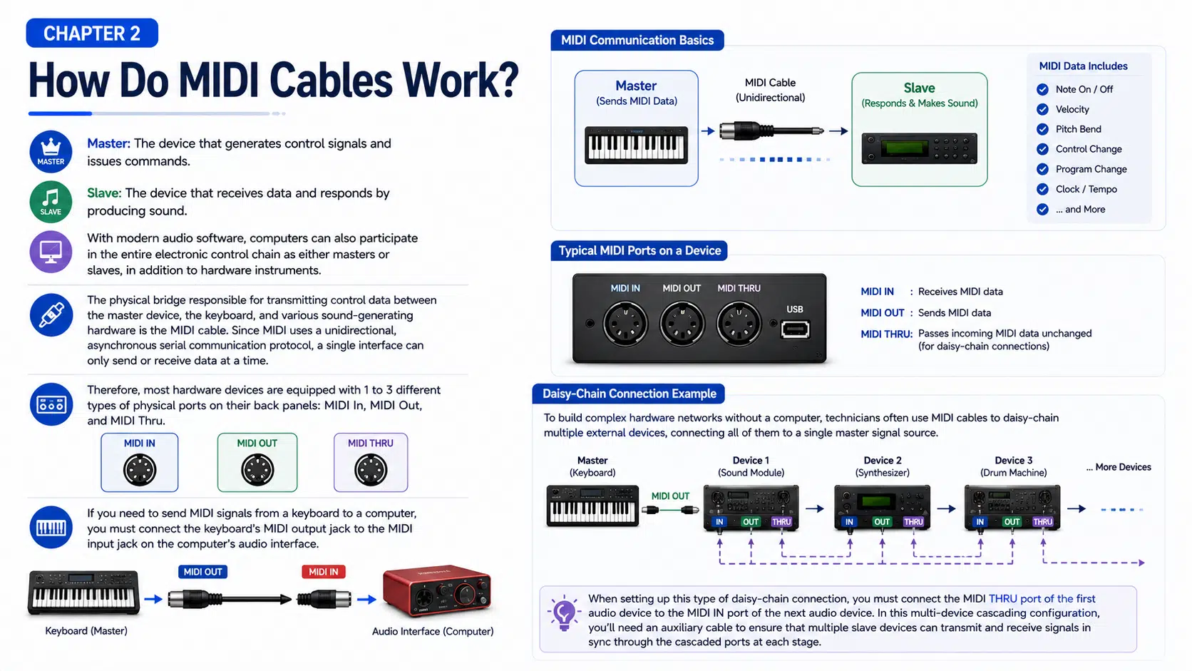
Not every Thru port is implemented in the same way. A hardware Thru may reproduce the incoming data through dedicated circuitry, while a soft Thru may route messages through firmware or software. Multiple devices in a chain can add delay, filtering, configuration risk, and more failure points. For larger systems, a powered MIDI distribution unit or interface with multiple outputs may be easier to validate.
| Assembly type | Passive or active | Main specification questions |
|---|---|---|
| 5-pin DIN to 5-pin DIN | Normally passive | Pinout, direction labels, length, connector orientation, cable construction, and strain relief |
| TRS to 5-pin DIN adapter | Normally passive when mapping is compatible | TRS size, Type A or Type B assignment, plug gender, DIN direction, and device model |
| USB-MIDI interface cable | Active | USB connector, interface chipset, MIDI ports, operating-system support, drivers, firmware, and power |
| MIDI breakout or fan-out harness | Passive or active depending on architecture | Branch mapping, labeling, common shield strategy, enclosure, connectors, and channel routing |
| Panel or equipment harness | Project-specific | Internal connector, panel receptacle, chassis grounding, retention, serviceability, and qualification requirements |
A straight 5-pin DIN MIDI cable is the simplest assembly when both devices use standard compatible DIN MIDI ports. Confirm whether the connector should be straight or right-angle and whether the equipment recess provides enough clearance. Direction labels are useful in installed systems even when the passive cable itself is electrically symmetrical.
Legacy MIDI guidance commonly references a maximum cable length of about 15 m, or 50 ft, for a compliant DIN-MIDI connection. Treat this as a standards-based design reference rather than a guaranteed installation distance. Transmitter and receiver implementation, cable capacitance, shielding, connectors, routing, grounding, and interference can change the practical result.
Some compact controllers, pedals, synthesizers, and interfaces use a 2.5 mm or 3.5 mm TRS connector for MIDI. TRS MIDI is not an analog stereo-audio connection, even though the plug looks similar. Type A and Type B assignments route the MIDI circuit to different TRS contacts, so the wrong adapter may fit but fail to communicate.
Specify the exact device model, TRS diameter, Type A or Type B mapping, plug or jack gender, and DIN direction. Do not infer the mapping from cable color or connector appearance. The guide to TS and TRS audio wiring explains why a TRS connector shape does not define its electrical function.
A USB-MIDI cable is not just a passive connector adapter. It contains interface electronics that translate between USB communication and MIDI ports. Compatibility depends on the chipset, firmware, USB descriptor, operating system, driver model, supported MIDI messages, port direction, power budget, and connected device.
Low-cost interfaces may use two DIN plugs labeled In and Out. These labels may describe the interface port or the device port to which it should connect, so follow the product documentation. Verify SysEx transfer, running status, timing behavior, power-up recovery, and the exact message set needed by the application.
For connector planning, review the USB connector types guide and the WIRES USB cable assembly page. USB-C connector shape alone does not establish USB mode, host role, power behavior, or MIDI compatibility.
For frequently handled stage or equipment cables, an overmolded cable assembly can improve strain transition and identification. The design still requires compatible materials, connector geometry, tooling, bend clearance, and validation against the intended use.
| Design factor | Risk if undefined | Required project input |
|---|---|---|
| Pin assignment | No communication, reversed direction, or equipment conflict | Approved schematic or connector table for both ends |
| Cable capacitance and length | Reduced signal margin in long or marginal DIN-MIDI links | Applicable MIDI specification, device data, installed route, and validation method |
| Shield and drain termination | Noise coupling, ground-current path, or inconsistent EMC behavior | System grounding plan and connector termination drawing |
| Conductor and insulation | Termination difficulty, excessive resistance, stiffness, or environmental damage | Electrical, flex, temperature, chemical, and diameter requirements |
| Connector orientation | Blocked ports, excessive bend, or interference with adjacent connectors | Equipment photos, CAD, and exit direction |
| Strain relief | Conductor fatigue or termination loading | Expected pulling, bending, handling, and service method |
| Labels and color coding | In/Out reversal and setup errors | Text, direction, device name, channel, color, and durability requirements |
Gold-colored contacts, oxygen-free copper, heavy braid, or a thick jacket should not be treated as proof of better MIDI performance. Use exact component part numbers, supplier data, released drawings, and system test results. The relevant design depends on whether the assembly is a passive DIN cable, a compact TRS adapter, an active USB interface, or part of a larger industrial AV cable assembly.
A passive cable does not create musical latency in the same way as software buffering, but transmission time, device processing, Thru implementation, daisy-chain depth, USB scheduling, drivers, and application buffers all contribute to the timing experienced by a performer.
Do not promise zero latency from cable construction. If timing is critical, test the complete chain with the intended controllers, instruments, interfaces, computers, software, message density, clock source, and operating conditions.
| Symptom | Possible causes | Checks |
|---|---|---|
| No MIDI response | Out connected to Out, wrong TRS mapping, incorrect adapter direction, damaged cable, disabled port, or unsupported device setting | Confirm Out-to-In routing, device model, Type A or B, port configuration, and a known-compatible cable |
| Notes are missing or stuck | Message overload, marginal connection, interface limitation, software filtering, daisy-chain issue, or device processing fault | Reduce the topology, capture MIDI data, compare direct and chained paths, and check message filters |
| Clock or timing is unstable | Multiple clock sources, soft-Thru routing, USB scheduling, software buffer, overloaded interface, or long chain | Select one clock source, simplify routing, review interface settings, and test with representative message traffic |
| USB-MIDI interface is not detected | Unsupported driver, damaged USB cable, insufficient power, hub issue, firmware, or operating-system policy | Connect directly, verify the USB port and driver, check device status, and test cold start and reconnect behavior |
| TRS adapter works with one device but not another | Different TRS diameter, Type A/Type B mapping, or manufacturer-specific wiring | Compare both manuals and adapter pin assignments rather than assuming interchangeability |
| Failure appears during stage movement | Connector side load, cable fatigue, intermittent termination, or inadequate strain relief | Inspect the installed route and connectors, substitute a verified cable, and document movement-related faults |
If the MIDI lead is integrated with audio, power, USB, control, or panel wiring, review the architecture using the wire harness and cable assembly selection guide. Separate the functions where needed and define grounding, shielding, connector service, and validation at the complete-system level.
| Stage | Evidence | Purpose |
|---|---|---|
| Design review | Approved drawing, BOM, connector views, pinout, labels, and risk list | Prevents direction and mapping assumptions before tooling or assembly |
| First article | Dimensions, continuity, pin mapping, workmanship, and visual records | Confirms the assembly matches the released definition |
| Functional validation | Exact devices, ports, messages, software, topology, and test sequence | Checks functions that a continuity test cannot prove |
| Mechanical validation | Project-defined bend, pull, flex, handling, and connector-retention methods | Relates mechanical evidence to the installation risk |
| Production release | Approved sample, tooling records, instructions, inspection plan, and change control | Maintains the validated construction across repeat builds |
WIRES can review the requirements through its custom cable process and build a prototype cable assembly for fit and system testing. Production requirements should define the necessary cable and harness quality controls; continuity alone does not prove MIDI timing, USB compatibility, software behavior, or complete-system reliability.
No. MIDI carries performance and control messages. The instrument’s analog or digital audio uses a separate audio connection unless a product implements another combined interface.
No. The connector shell may also be used for other equipment and pin assignments. Confirm that the cable construction and wiring match the applicable MIDI connection and both devices.
A standard passive DIN-to-DIN cable may be electrically symmetrical, but the system connection is directional: Out or Thru connects to In. Custom breakouts, active interfaces, and labeled assemblies may have a defined direction.
No. They use different contact mappings. A correctly sized plug can still fail if the adapter type does not match the device. Check the device manual and adapter pinout.
No. A USB-MIDI interface contains active electronics and may depend on firmware, drivers, operating-system support, power, and the MIDI messages required by the application.
Legacy DIN-MIDI guidance commonly references about 15 m or 50 ft under compliant conditions, but this is not a guarantee for every device or installation. Confirm the applicable specification, equipment implementation, cable data, route, and system test.
Provide device models, port photos, MIDI transport, pinout, direction, connector part numbers, length, orientation, environment, labels, expected order range, and required inspection and functional tests.
Send WIRES the connected device models, clear port photographs, connector and pinout requirements, finished length, routing conditions, direction labels, and validation plan. Contact WIRES to review whether the project needs a passive DIN or TRS assembly, an active USB-MIDI interface architecture, a breakout harness, or an integrated cable assembly.
 English English
 Vietnamese
 Indonesian
 Arabic
 Spanish