Car audio wire harness colors are a useful starting point, not proof of circuit function. Many aftermarket head-unit pigtails use familiar colors for battery power, accessory power, ground, remote turn-on, illumination, and speaker pairs. Vehicle-side wiring can follow completely different OEM schemes, and even aftermarket interfaces can vary. Confirm every connection against the head-unit manual, vehicle service information, adapter documentation, and test results before applying power.
This guide explains the common aftermarket convention, the limits of color matching, and a safer verification workflow. For the wider vehicle system context, see the car electrical wiring harness guide.
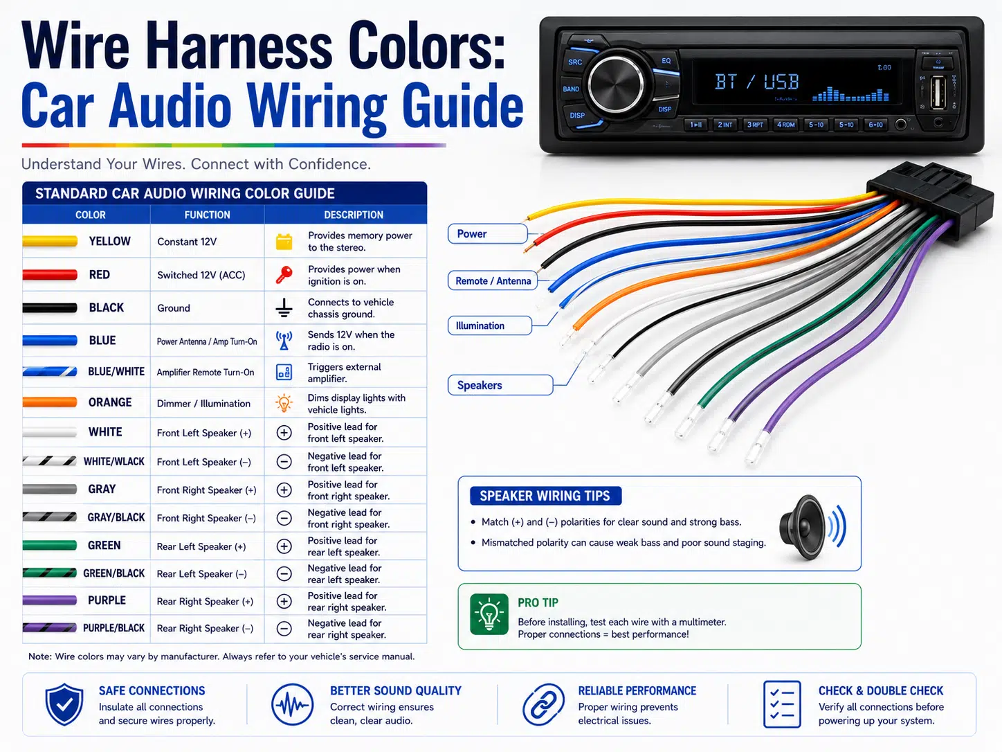
On many aftermarket radio harnesses, solid-color speaker wires are used for positive leads and the same color with a black stripe is used for the corresponding negative lead. Power and control colors often follow the table below. These are conventions, not universal OEM rules.
| Common aftermarket color | Typical function | What must be verified |
|---|---|---|
| Yellow | Constant battery supply or memory feed | Head-unit manual, fuse protection, vehicle adapter pinout, and measured circuit behavior |
| Red | Accessory or switched turn-on supply | Whether the vehicle provides a discrete switched circuit or requires a data interface |
| Black | Ground or negative reference | Approved ground pin or chassis point and low-resistance connection |
| Blue | Power antenna control on some radios | Output function and current limit in the radio manual |
| Blue/white | Amplifier or accessory remote turn-on on many radios | Compatible control input and permitted load |
| Orange or orange/white | Illumination or dimmer function on some radios | Vehicle and radio interface type; do not assume analog compatibility |
| White / white-black | Front-left speaker pair | Polarity, channel, factory amplifier topology, and speaker load |
| Gray / gray-black | Front-right speaker pair | Polarity, channel, factory amplifier topology, and speaker load |
| Green / green-black | Rear-left speaker pair | Polarity, channel, factory amplifier topology, and speaker load |
| Purple / purple-black | Rear-right speaker pair | Polarity, channel, factory amplifier topology, and speaker load |
| Other colors | Mute, steering-wheel controls, reverse, parking-brake, camera, data, or manufacturer-specific functions | Exact product documentation; never infer these circuits from color alone |
A nominal 12 V passenger-vehicle system does not mean every wire is a simple 12 V supply. Modern vehicles may use data messages, pulse-width-modulated signals, low-current sensing circuits, factory amplifiers, and protected electronic outputs. Color matching without circuit verification can damage the radio, an interface module, or vehicle electronics.
A stereo harness connects a head unit or audio interface to the vehicle wiring without requiring every circuit to be joined individually at the dashboard. Depending on the vehicle, it may be a passive adapter, an extension, a repair pigtail, or an active interface containing electronics.
A complete assembly can include conductors, insulation, terminals, connector housings, strain relief, labels, shielding, protective sleeving, and an electronic module. The general wire harness component guide explains how these parts work together.
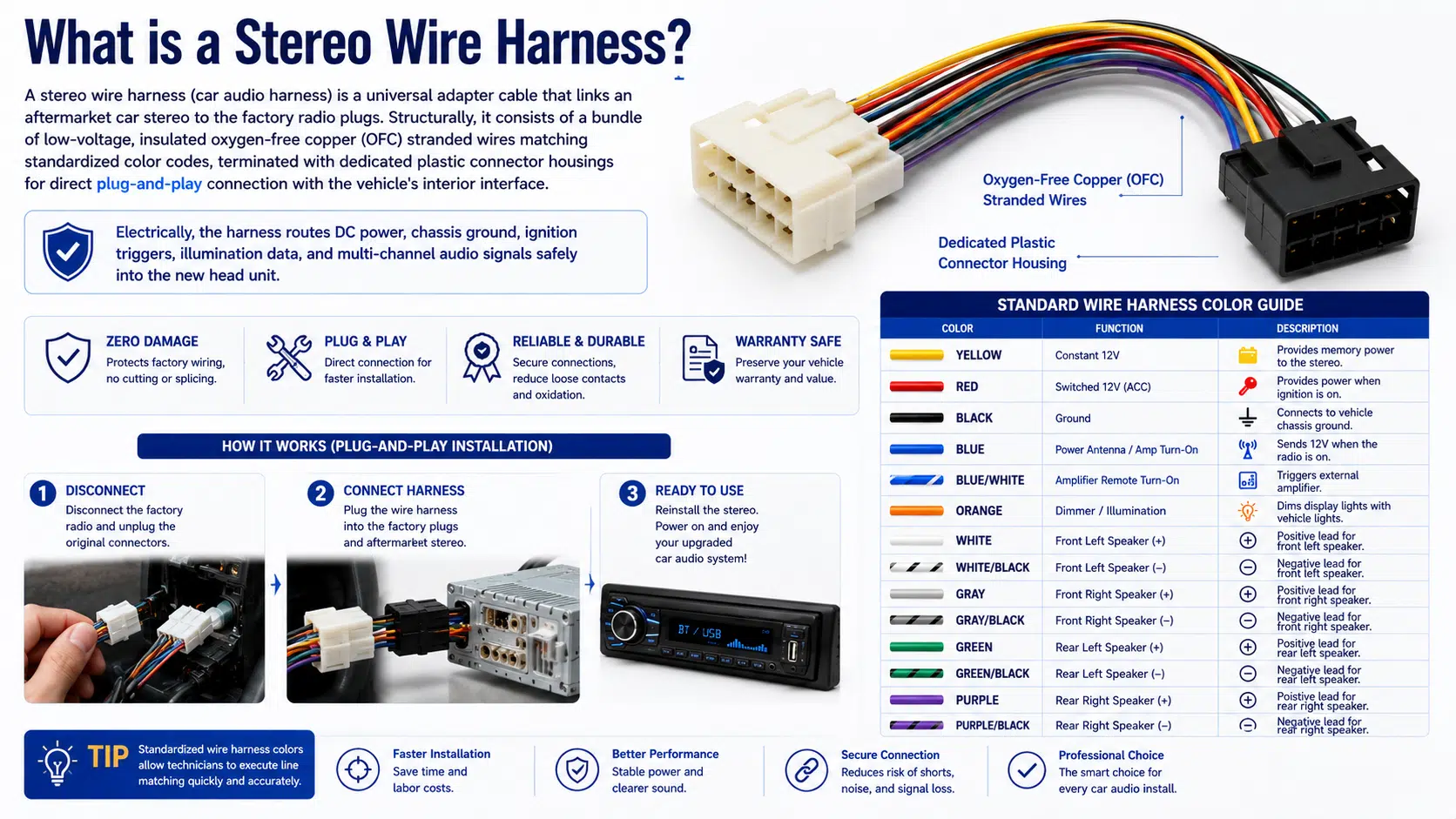
Many aftermarket brands use a similar color convention because it simplifies installation and service. The radio manual remains the controlling reference. A familiar color does not override the pinout printed for that model.
Vehicle manufacturers select their own colors, connector families, cavity assignments, splices, option packages, and production changes. The same model name can have different wiring across years, trim levels, regions, factory audio systems, and mid-cycle revisions.
An adapter maps the vehicle connector to an aftermarket convention, but it must match the exact vehicle and factory equipment. A plug that physically fits may still have a different pinout or omit required electronics.
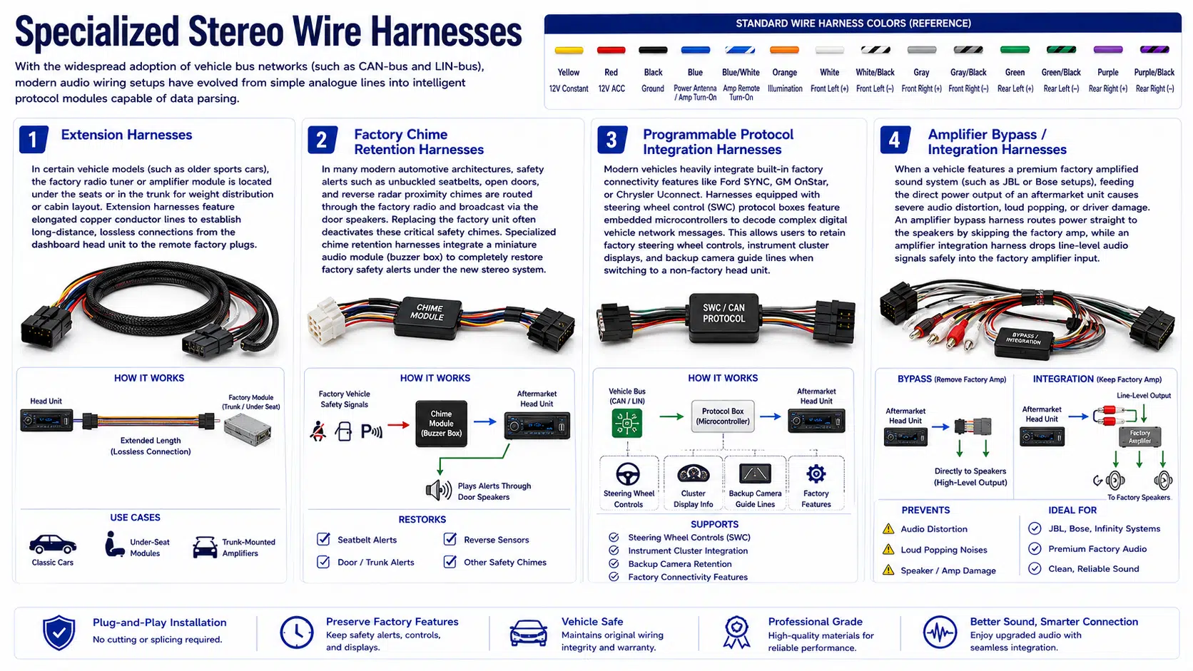
Some vehicles use CAN, LIN, or another network to control radio power, retained accessory operation, chimes, steering-wheel buttons, amplifiers, cameras, or displays. These installations may require a compatible interface module rather than a direct color-to-color connection.
If the project involves a custom adapter rather than an off-the-shelf pigtail, use the same drawing and revision control expected for an engineered cable assembly.
An extension carries circuits between the dashboard and a remote tuner, amplifier, control module, or relocated head unit. Conductor size, length, routing, connector retention, voltage drop, and noise exposure must suit the application. It should not be described as lossless without project-specific evidence.
Some interfaces reproduce warning chimes or retain accessory behavior after the factory radio is removed. Compatibility depends on the vehicle, software, option package, and interface revision. Safety-related functions should be confirmed before the vehicle returns to service.
A programmable module may translate vehicle network messages into commands understood by the new radio. Firmware, radio brand, button mapping, and installation configuration all affect compatibility.
An integration harness can preserve a factory amplifier by providing the signal level, turn-on control, and channel mapping it expects. A bypass harness routes around the amplifier only when the vehicle wiring and speaker arrangement support that design. Do not connect speaker-level outputs to an unknown factory-amplifier input.
A reverse harness restores a cut or damaged factory radio connector. Repair work should follow the correct cavity map, terminal system, wire size, sealing, strain relief, and inspection criteria.
Vehicle electrical work can affect airbags, anti-theft systems, retained-accessory circuits, electronic modules, and stored fault codes. Follow the vehicle and equipment service instructions rather than a generic battery-disconnection rule.
No single joining method is best for every vehicle. A correctly engineered crimp can provide repeatable mechanical and electrical performance. Solder may be permitted in some repair or aftermarket instructions, but poor soldering can wick into the conductor, reduce flexibility, create sharp points, or leave an unsupported joint.
Terminal selection should match the connector housing, wire range, conductor construction, plating system, tooling, and acceptance criteria. See the wire harness terminal guide for crimp and material considerations. For small connector systems, the JST connector selection guide illustrates why pitch, terminal, housing, and mating part must be treated as one system.
| Symptom | Possible causes | Checks |
|---|---|---|
| Radio does not power on | Missing constant supply, missing switched signal, poor ground, open fuse, incompatible data interface | Verify the manual, adapter mapping, fuses, ground path, and interface status |
| Radio loses presets | Constant and switched feeds reversed or constant feed unavailable | Confirm circuit behavior with approved test methods |
| One or more speakers are silent | Wrong channel mapping, open circuit, factory amplifier issue, damaged speaker, connector fault | Trace the channel from radio output through adapter, amplifier, and speaker |
| Weak bass or unclear stereo image | Speaker polarity mismatch or incorrect channel pairing | Verify every speaker pair against the drawing |
| Amplifier stays on | Remote output connected to the wrong circuit or interface configuration error | Check radio output behavior and amplifier-control requirements |
| Pop, whine, or hum | Grounding, routing, gain, amplifier integration, shield, or charging-system interaction | Use a structured diagnosis; the audio ground-loop troubleshooting guide explains the same system-level approach |
| Chimes or steering controls fail | Wrong interface, configuration, firmware, or vehicle option selection | Confirm compatibility and programming with the interface supplier |
| Connector becomes hot | Excess current, poor contact, wrong terminal, damaged housing, undersized conductor, or bad crimp | Stop using the circuit and inspect it before further operation |
Speaker outputs, line-level interconnects, USB extensions, microphones, antennas, cameras, and amplifier links have different electrical requirements. Connector shape alone does not define the signal. For analog line connections, compare the TS and TRS wiring guide with the radio and amplifier documentation.
Review the WIRES product range and the custom harness development process when preparing a request. A prototype cable assembly should be checked in the exact vehicle and equipment configuration before production release. Inspection and acceptance should follow a documented wire harness quality plan.
For factory connector cavities, OEM pinouts, amplifier integration, data interfaces, and feature-retention decisions, see the factory car stereo wiring harness identification and adapter guide.
No. Aftermarket radio pigtails often use a familiar convention, but vehicle OEM colors and pin assignments vary by manufacturer, model, year, trim, region, and factory audio package.
No. Match each circuit by documented function and connector cavity, then verify it with approved test methods. A color match can still connect two different functions.
Black is commonly used for ground on aftermarket radio pigtails, but it is not a universal rule for every vehicle or module. Confirm the exact diagram and ground path.
The factory radio may receive power-state, chime, steering-control, amplifier, camera, or display information over a vehicle network. A compatible interface translates those functions for the aftermarket equipment.
A vehicle-specific adapter is usually easier to document, reverse, and service. If the original connector is already damaged, use an approved repair method and preserve the correct cavity assignments and wire specifications.
Only when the vehicle wiring, speaker impedance, channel layout, and new equipment support the bypass design. Some systems require an integration interface instead.
No single conductor label guarantees system performance. Conductor size, resistance, length, terminals, joints, routing, amplifier design, speaker load, installation quality, and the complete signal path all matter.
Use car audio wire harness colors as labels within a verified wiring plan, not as the plan itself. Identify the exact vehicle and factory system, compare every pinout, retain the original connector where practical, select compatible interfaces, and test the completed functions before final assembly.
For a custom adapter or integration harness review, send the vehicle configuration, equipment models, connector details, pinout, drawings, and acceptance requirements through the WIRES contact page.
 English English
 Vietnamese
 Indonesian
 Arabic
 Spanish