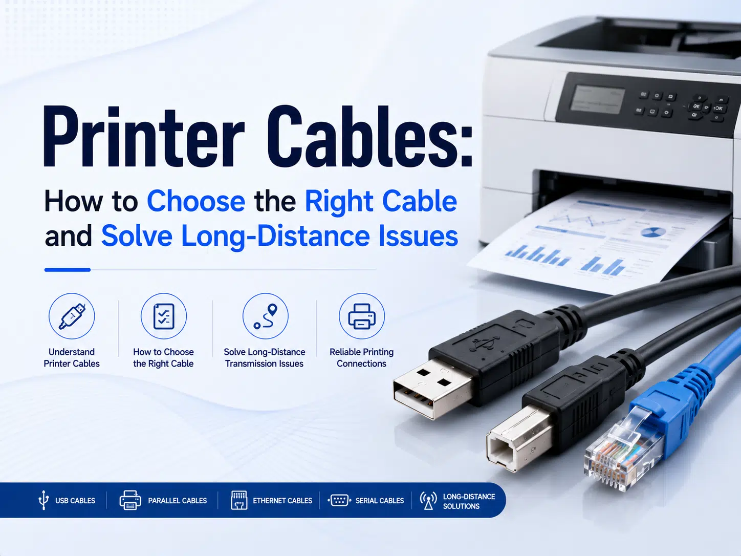
A printer cable should be selected by the interfaces on the host and printer, the required distance, the installation environment, and the driver or protocol that the equipment actually supports. USB A-to-B is common for local desktop printers, while legacy parallel, RS-232 serial, FireWire, Ethernet, and active extension systems apply only to compatible equipment. For a long run, do not assume that a thicker passive cable or a plug-shaped adapter will solve the problem. Confirm the complete connection path and validate it with the exact printer, host, software, and operating environment.
This guide explains the main printer cable types, how to choose a connection for short and long distances, why some adapters fail, and what information a cable supplier needs before building a custom assembly. For a closer look at the square USB Type-B interface, see the USB A-B printer cable guide.
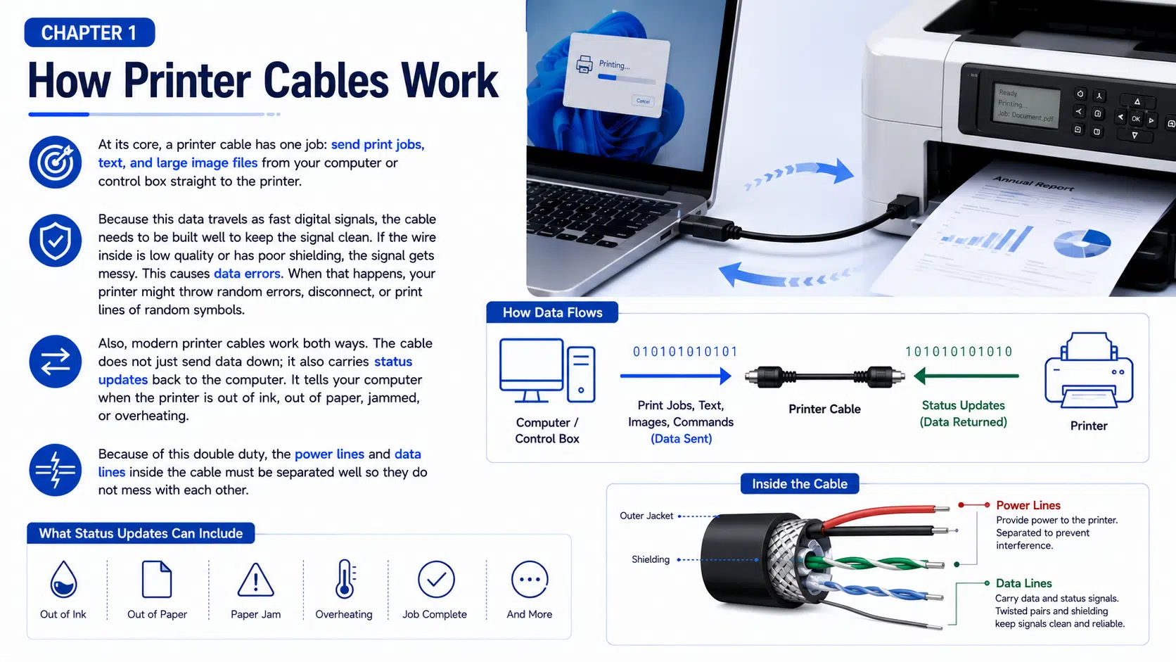
A printer connection carries commands and print data from a computer, controller, point-of-sale terminal, or print server to the printer. Depending on the interface and printer protocol, the return path may also carry device identification, job status, paper or consumable warnings, and error information.
The connector shape alone does not define the complete connection. Reliable operation also depends on the electrical interface, pinout, cable construction, driver, firmware, operating-system support, device settings, and any adapter or extender in the path. A cable cannot correct an unsupported protocol or a missing driver.
| Connection factor | What must match | Common result when it does not match |
|---|---|---|
| Connector | Plug type, receptacle shape, keying, and orientation | The cable cannot mate or is mechanically unstable |
| Electrical interface | USB, RS-232, IEEE 1284, IEEE 1394, Ethernet, or another specified interface | No enumeration, no communication, or possible equipment risk |
| Protocol and driver | Printer language, host driver, adapter chipset, and operating-system support | The device appears unknown, offline, or unavailable |
| Pinout and configuration | Straight-through or crossed wiring, handshaking, gender, and device-specific assignments | Intermittent communication or no data transfer |
| Installation | Distance, routing, motion, grounding, temperature, chemicals, and mechanical load | Errors that appear only after installation or during machine operation |
There is no universal printer cable. Read the labels and manuals for both devices before ordering. The following comparison is a selection starting point rather than a substitute for the printer manufacturer’s documentation.
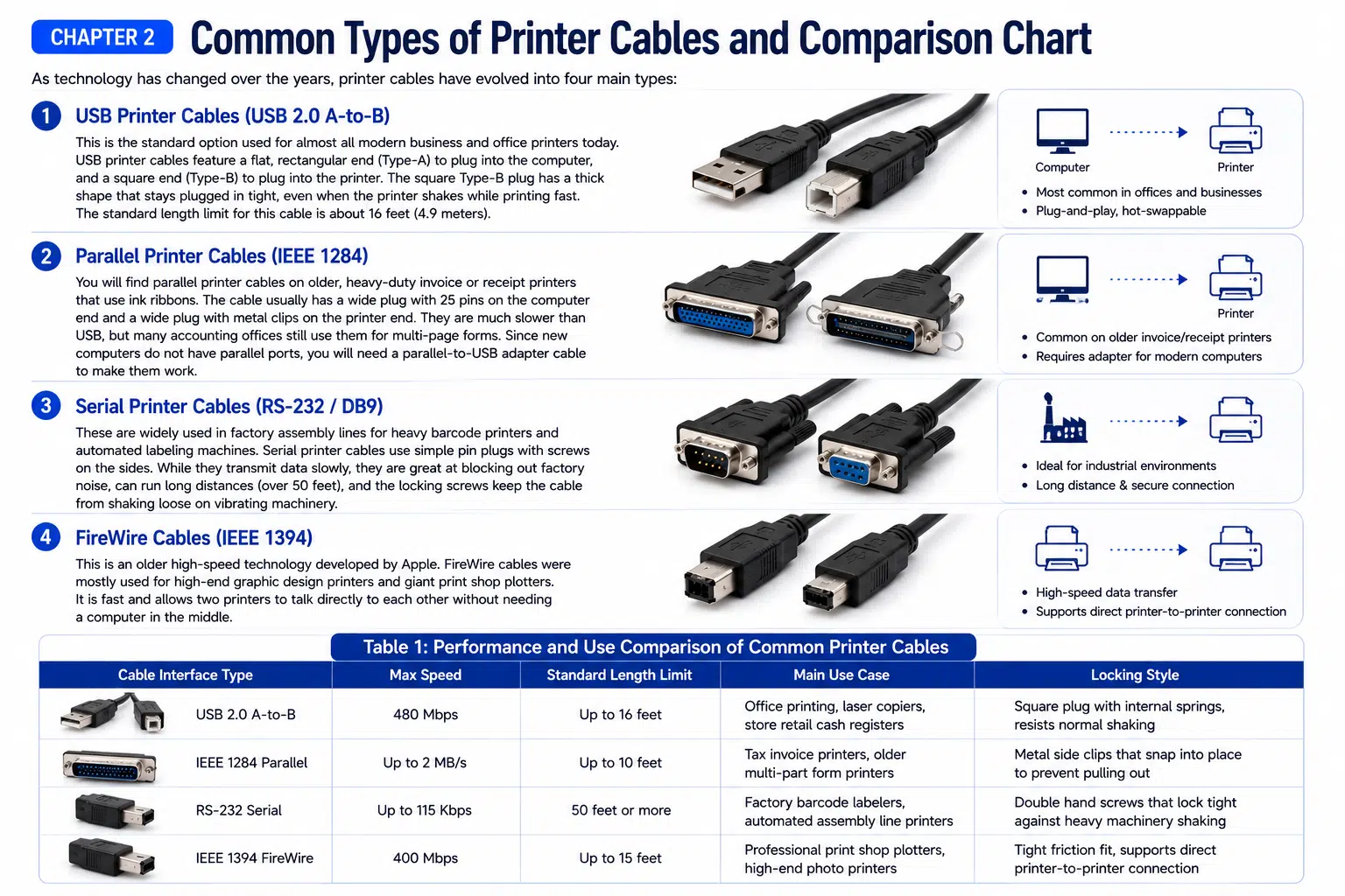
| Interface | Typical connector | Where it is used | Important selection limit |
|---|---|---|---|
| USB | USB Type-A to USB Type-B, or another device-specific USB combination | Office printers, label printers, multifunction devices, and service equipment | The connector generation, data mode, host port, printer receptacle, passive length, and driver must all be compatible |
| IEEE 1284 parallel | DB25, Centronics-style, or another specified parallel connector | Legacy printers, industrial controllers, and older point-of-sale systems | Connector gender, pinout, interface mode, host hardware, and adapter support vary |
| RS-232 serial | Often DB9, but other connectors and custom pinouts are common | Barcode, receipt, label, and industrial printers | DTE/DCE arrangement, straight or null-modem wiring, baud rate, handshaking, ground reference, and pinout must be defined |
| IEEE 1394 FireWire | 4-pin, 6-pin, or 9-pin depending on the device generation | Specific legacy imaging or printing equipment | Use only when the equipment explicitly supports FireWire; a passive USB adapter cannot convert the protocol |
| Ethernet network connection | RJ45 or an industrial network connector | Shared printers and installations where the printer has a network interface | This is a network architecture, not a passive USB extension; printer configuration, addressing, security, and network support are required |
USB A-to-B is the familiar local-printer connection. A conventional USB 2.0 interface has a theoretical signaling rate of up to 480 Mbit/s, but that number is an interface limit rather than a guaranteed print-transfer rate. Printer electronics, protocol overhead, host software, hubs, adapters, and the print job all affect real operation.
Standard USB 2.0 Type-B and the larger SuperSpeed USB 3.x Type-B receptacle are mechanically different. A cable should never be selected from the words USB printer cable alone. Compare the actual receptacle, device manual, and required USB mode. The WIRES guide to USB connector types provides a broader connector comparison.
Parallel printer interfaces remain in some legacy equipment. The term parallel cable does not identify one connector or pinout. DB25-to-Centronics combinations are familiar, but equipment-specific variants exist. Before replacing a cable, record both connector faces, genders, latch style, pin assignment, and the host interface mode.
A USB-to-parallel product normally contains active conversion electronics and requires compatible drivers. A cable with the correct-looking plugs is not proof that the printer language, host software, or operating system will work.
Serial links can be useful in industrial and point-of-sale systems because the configuration is explicit and screw-locking connectors are available. However, DB9 does not automatically mean RS-232, and two RS-232 devices may still require different wiring. Confirm signal direction, DTE/DCE roles, straight-through or null-modem routing, hardware or software handshaking, baud rate, parity, stop bits, and ground reference.
Distance capability depends on data rate, cable capacitance, driver and receiver characteristics, grounding, routing, and the electrical environment. Do not use a universal distance claim without the exact equipment specification and a tested installation.
FireWire is now a legacy interface, but it may remain necessary for a specific printer, scanner, imaging device, or print-production system. Confirm the 4-pin, 6-pin, or 9-pin connector and the supported IEEE 1394 generation. Review the FireWire cable types guide and the separate guide on connecting FireWire to modern computers before planning a migration.
A passive FireWire-to-USB cable does not translate between IEEE 1394 and USB. A workable migration may require a supported host controller, an approved Thunderbolt path, device drivers, or replacement equipment.
For assemblies exposed to pulling, vibration, or frequent handling, an overmolded cable assembly can integrate strain relief and connector protection. The overmold design still needs to be checked for material compatibility, bend transition, tooling, service clearance, and the connector manufacturer’s limits.
Long-distance printer communication is a system-design problem. Increasing conductor size does not automatically extend a high-speed data interface, and adding shielding does not repair timing, attenuation, protocol, or driver limitations.
| Long-distance option | When it may fit | What to verify |
|---|---|---|
| Shorter passive cable and relocated host | The host or print server can be installed closer to the printer | Power, access, ventilation, security, and maintenance |
| Powered USB hub or active USB extension | The printer and host support USB and the extender is designed for the required mode | Maximum topology, hub count, power supply, USB mode, driver support, latency, and recovery after power cycling |
| USB extender over copper or fiber | Industrial or commercial runs beyond a normal passive USB arrangement | Extender pair compatibility, supported USB class, cable medium, power at both ends, grounding, isolation, and environmental rating |
| Ethernet or print server | The printer has a network interface or a supported print server is available | Printer protocol, network configuration, cybersecurity policy, addressing, drivers, and bidirectional status functions |
| RS-232 connection | The printer and host natively support a defined serial interface | Pinout, baud rate, handshaking, cable capacitance, grounding, and tested distance |
| Equipment migration | Legacy adapters and drivers create unacceptable service risk | Printer features, software integration, validation records, consumables, and change-control requirements |
For conventional passive USB 2.0 A-to-B installations, approximately 5 m is often used as a practical design reference for a single compliant high- or full-speed cable segment. Treat this as a starting point, not a promise. USB generation, cable delay, conductor construction, connector loss, hubs, host controller, device sensitivity, and the applicable USB specification determine whether a particular channel is acceptable.
Do not join several passive extension cables and assume the result remains compliant. Every connector and cable section adds loss, delay, mechanical risk, and another possible ground or shielding discontinuity.
An active USB cable, repeater, or extender regenerates or converts the signal using electronics. This can support a longer installed route, but it introduces power, chipset, compatibility, recovery, and thermal considerations. Verify that the product supports the printer’s USB class and data mode. Test cold start, restart, sleep and wake, cable disconnection, large print jobs, status reporting, and fault recovery.
In electrically noisy or ground-potential-sensitive installations, a fiber-based extender may provide useful isolation between locations, but it is still an active system. The complete extender documentation and equipment validation remain necessary.
If a printer has a supported Ethernet interface, a network connection may be more maintainable than stretching a local USB connection. Network printing also supports shared access, but it introduces configuration and security responsibilities. Confirm the printer protocol, network policy, driver deployment, addressing, bidirectional status support, and behavior after network interruption.
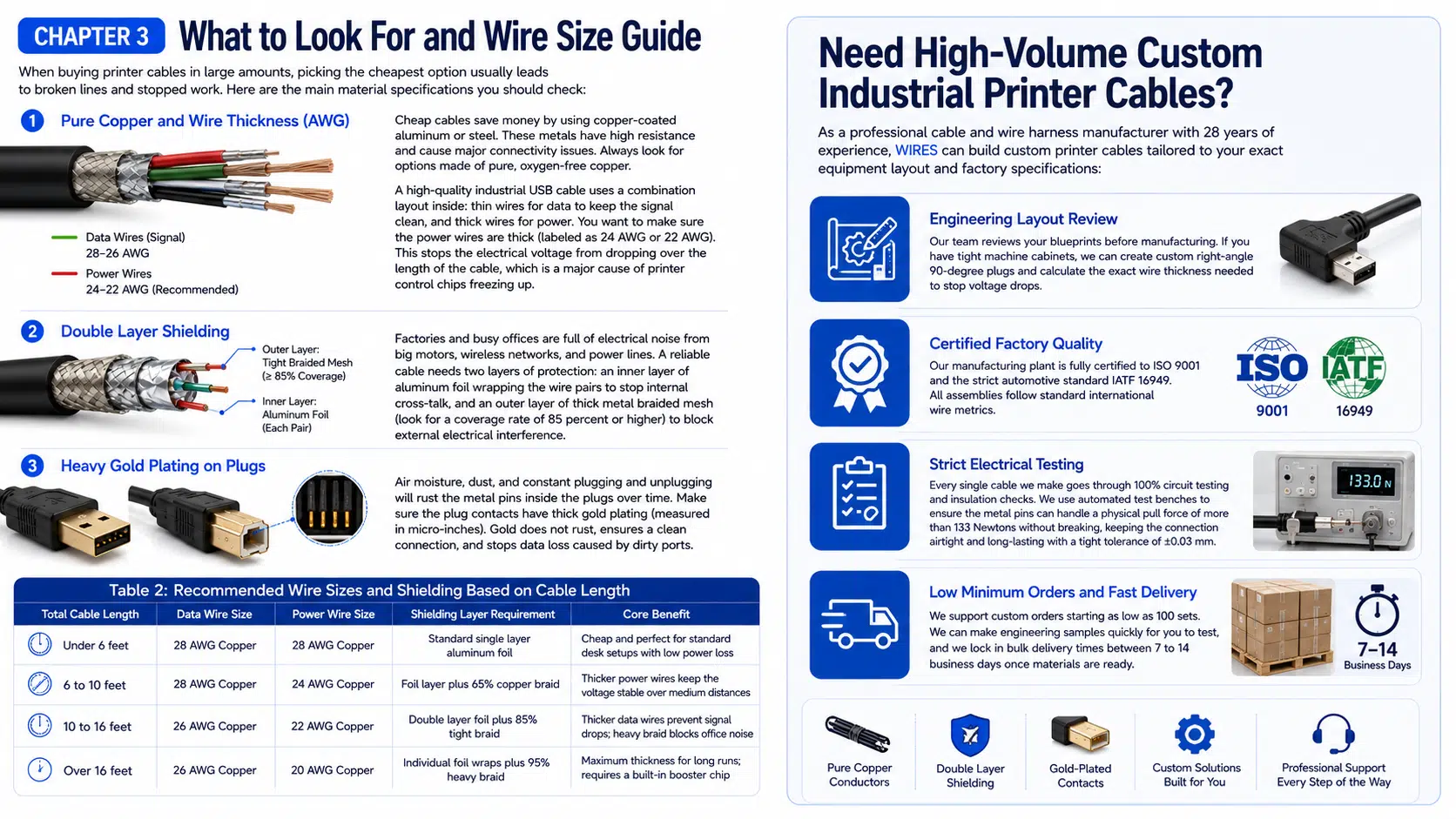
| Construction item | Why it matters | Evidence to request |
|---|---|---|
| Conductor material and size | Affects resistance, voltage drop, flex behavior, termination, and cable diameter | Approved drawing, conductor specification, and measured resistance under stated conditions |
| Data-pair geometry | Affects impedance, skew, attenuation, and susceptibility to noise | Interface-specific cable construction and validation method |
| Shield and drain termination | Affects EMC behavior and ground-current paths | Shield construction, coverage method, connector termination, and system grounding plan |
| Connector contacts and plating | Affects mating compatibility, corrosion behavior, contact resistance, and wear | Exact connector part number and manufacturer specification |
| Jacket and insulation | Affects temperature, flexibility, abrasion, chemical exposure, and regulatory evidence | Material designation, supplier data, and project-specific environmental requirements |
| Strain relief and overmold | Affects bend transition, pull loading, sealing concept, and service life | Drawing, tooling concept, bend and pull test method, and acceptance criteria |
Oxygen-free copper, gold-colored contacts, a large cable diameter, or a high shielding percentage should not be treated as automatic proof of performance. The complete design and the interface-specific test results matter more than a single marketing feature. For power-related conductor selection, use the custom power cable design guide as a separate reference; power-cable rules should not be applied directly to high-speed data pairs.
Start with the simplest controlled checks. Avoid replacing several parts at once because that removes evidence about the actual failure.
| Symptom | Possible causes | Practical checks |
|---|---|---|
| Printer is not detected | Wrong port, damaged connector, unsupported adapter, missing driver, failed hub, or printer power issue | Confirm the port and interface, inspect the connector, connect directly, review device status, and test a known-compatible cable |
| Printer repeatedly goes offline | Loose connection, power management, hub or extender reset, driver issue, grounding, or intermittent cable damage | Check event timing, remove optional adapters, secure connectors, review power settings, and flex the cable only under a controlled inspection |
| Small jobs work but large jobs fail | Marginal signal channel, extender buffer or power issue, driver problem, software timeout, or network interruption | Repeat a defined job, compare direct and extended paths, review logs, and test after cold start |
| Garbled characters on a legacy printer | Incorrect serial parameters, wrong parallel mode, pinout mismatch, printer-language issue, or software configuration | Verify interface settings and pinout against both manuals; do not assume the cable is the only cause |
| Failure occurs when machinery runs | EMI coupling, ground potential, vibration, connector movement, or shared power disturbance | Correlate the fault with machine events, inspect routing and grounding, separate test paths, and capture repeatable evidence |
| Connection fails after an operating-system update | Driver, adapter chipset, permission, or security-policy change | Review supported driver versions, device manager or system logs, and the adapter manufacturer’s compatibility information |
For mixed-signal equipment or custom routing near industrial machinery, the industrial AV cable assembly guide explains shielding, grounding, distance, motion, and validation decisions in more detail.
A useful request for quotation should define the system rather than ask for a premium printer cable. Include the following information:
When the printer lead becomes part of a larger routed assembly, compare the architecture with the wire harness and cable assembly selection guide. A prototype should use intended connectors, cable, overmold materials, labels, and tooling wherever those choices can affect fit or performance. WIRES can review the requirements through its customized cable process and support a prototype cable assembly before production release.
| Stage | Suggested evidence | Why it is needed |
|---|---|---|
| Design review | Approved drawing, BOM, pinout, interface definition, and risk list | Prevents connector, wiring, and application assumptions from reaching production |
| First article | Dimensions, workmanship, continuity, resistance where applicable, and visual records | Confirms that the built assembly matches the released design |
| System validation | Exact host, printer, software, representative jobs, adapters, and installed route | Checks functions that a standalone continuity test cannot prove |
| Environmental validation | Project-defined temperature, flex, vibration, chemical, abrasion, or EMC methods | Connects test conditions to the real installation risks |
| Production release | Approved samples, work instructions, tooling records, inspection plan, and change control | Maintains the validated construction across repeat orders |
Continuity testing can find open, shorted, or miswired circuits, but it does not prove USB signal margin, serial configuration, driver compatibility, print quality, network behavior, or complete-system reliability. Define the required evidence in the purchasing specification and review the supplier’s wiring harness quality controls before release.
USB Type-A to USB Type-B is common for local desktop and office printers, but many current printers also use Ethernet, Wi-Fi, USB-C, or device-specific interfaces. Check the exact printer model and port before ordering.
No. The connectors may fit while the USB generation, cable construction, length, host port, printer receptacle, hub, adapter, or driver remains incompatible. Confirm the device documentation and test the complete connection.
There is no safe universal answer for every USB generation and installation. Approximately 5 m is often used as a practical reference for one conventional passive USB 2.0 high- or full-speed segment, but the applicable USB specification, cable construction, device design, hubs, and validation determine the acceptable length.
Not necessarily. Larger power conductors may reduce voltage drop, but high-speed data also depends on impedance, attenuation, delay, skew, connectors, topology, and device tolerance. An active extender, network connection, or equipment relocation may be more appropriate.
No. Different protocols normally require active conversion electronics, compatible drivers, and explicit support for the printer. Connector shape alone cannot perform protocol conversion.
The longer path may add signal loss, delay, connector discontinuities, insufficient power, hub or repeater compatibility issues, or greater exposure to installation noise. Compare the direct and extended paths with the same host, printer, driver, and print job.
Send the host and printer models, clear port photos, interface and pinout, installed length, connector orientation, retention, environment, routing, labels, expected order range, and required validation methods. Do not rely only on a generic cable name.
WIRES can review a custom printer cable or printer-related cable assembly against your drawing, equipment interfaces, route, connector orientation, environment, and validation plan. Claims about compliance, performance, testing, minimum order, or delivery should be agreed from documented project requirements rather than assumed from a standard product description.
Contact WIRES with the printer model, host interface, port photos, required length, installation conditions, and test expectations. The engineering review can then identify whether the project needs a passive cable, overmolded assembly, active extension architecture, legacy-interface adapter, or a broader harness solution.
 English English
 Vietnamese
 Indonesian
 Arabic
 Spanish