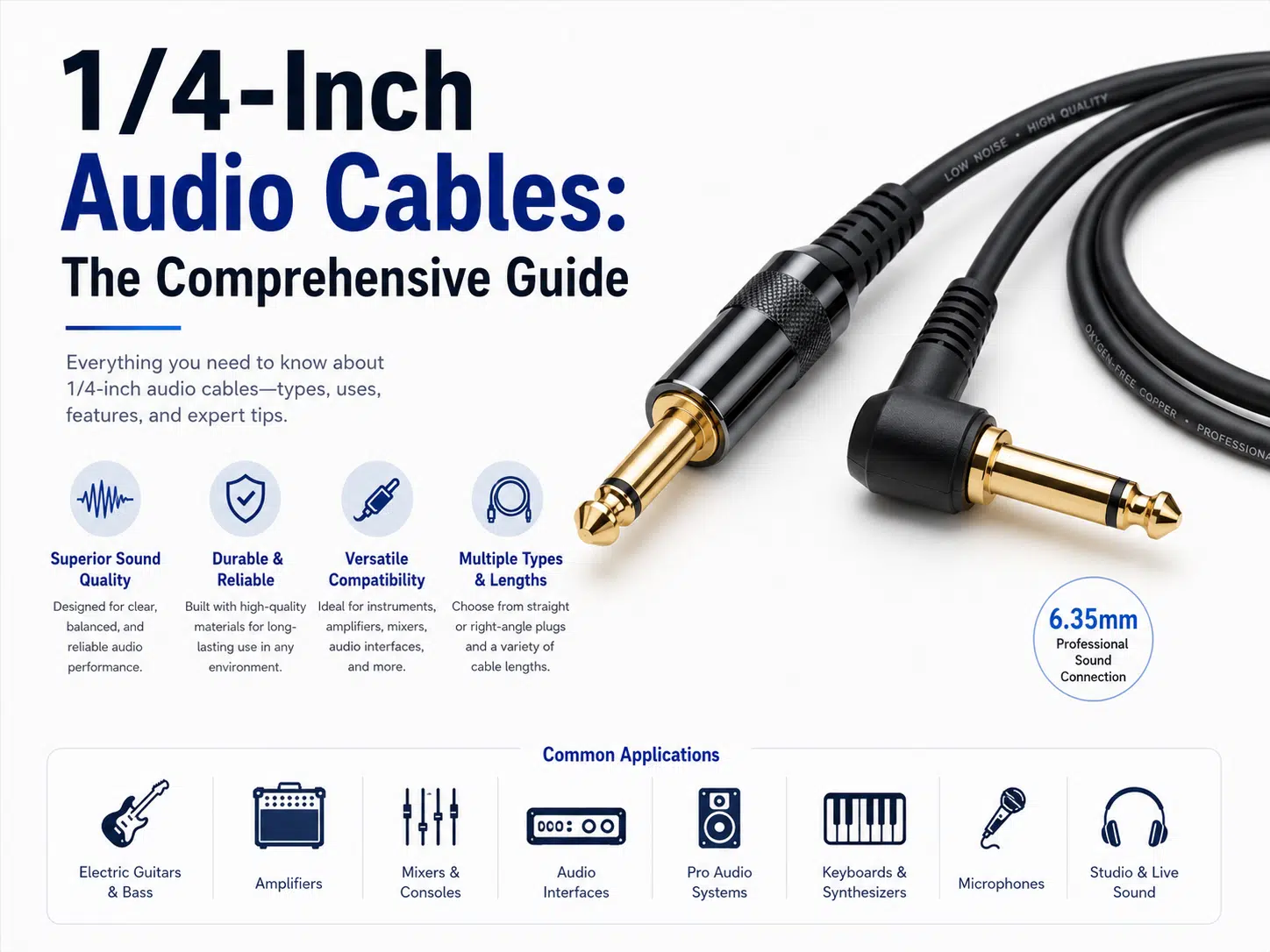
Quick answer: A 1/4-inch audio cable uses the connector commonly called a 6.35 mm phone plug. TS plugs have two contacts and are commonly used for unbalanced mono instruments or speaker connections, while TRS plugs have three contacts and can carry balanced mono, unbalanced stereo, insert send/return, or control signals. The plug shape alone does not determine the signal format or cable construction.
Choose a cable from the equipment input and output labels, pinout, signal level, balanced or unbalanced circuit, conductor construction, shielding, length, flexibility, and mechanical load. A guitar cable, balanced line cable, headphone cable, and speaker cable can all use 1/4-inch plugs but are not interchangeable in every application.
For terminology and construction differences, see the wire harness and cable assembly guide.
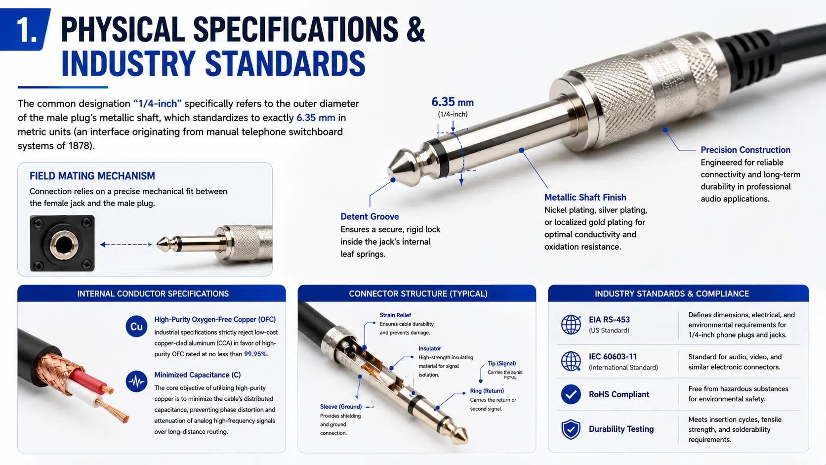
The term “1/4-inch” refers to the nominal plug size and is commonly expressed as 6.35 mm. It describes the connector family, not the internal wiring, signal level, impedance, shielding, or power capability.
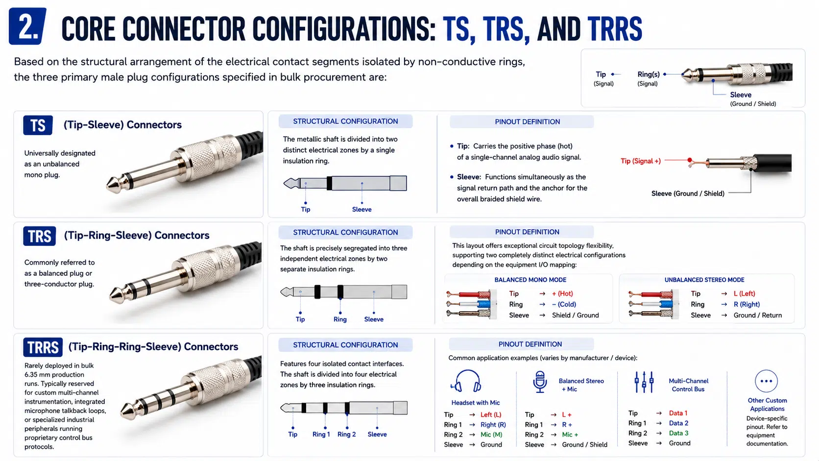
The plug has conductive sections separated by insulation rings. The number of sections creates the common TS, TRS, and TRRS names:
| Connector | Contacts | Common audio uses | Important caution |
|---|---|---|---|
| TS: Tip-Sleeve | 2 | Unbalanced mono instrument, line, footswitch, or speaker connection | Instrument and speaker cables may use the same plug but need different cable construction |
| TRS: Tip-Ring-Sleeve | 3 | Balanced mono, unbalanced stereo, insert send/return, headphone, or control connection | A TRS plug is not automatically balanced; both equipment interfaces must support balanced wiring |
| TRRS: Tip-Ring-Ring-Sleeve | 4 | Specialized headset, intercom, multi-channel, or proprietary equipment | Several incompatible pinout conventions exist; verify the equipment documentation |
A TS connector has a tip and sleeve separated by one insulation ring. In a common unbalanced audio circuit, the tip carries the signal and the sleeve is the return and shield connection. TS is widely used for electric guitar, bass, keyboards with unbalanced outputs, effects pedals, and some mono line connections.
A TS plug is also used on many passive speaker cables. That does not make an instrument cable suitable for a speaker load. Instrument cable is normally shielded and optimized for a low-level, high-impedance signal. Speaker cable normally uses two larger conductors and may be unshielded because it carries higher current from an amplifier to a passive speaker.
A TRS connector has tip, ring, and sleeve contacts separated by two insulation rings. Its function depends on the equipment:
A TRS cable only provides a balanced audio link when the source output, cable wiring, and destination input all use the compatible balanced circuit. Using a TRS plug does not convert an unbalanced source into a balanced signal.
| Application | Typical connector | Cable construction | Selection priority |
|---|---|---|---|
| Electric guitar or bass | TS | Shielded unbalanced instrument cable | Capacitance, flexibility, handling noise, shielding, connector strain relief |
| Balanced line between audio equipment | TRS | Two insulated signal conductors plus shield | Correct balanced interfaces, pair geometry, shield termination, connector quality |
| Stereo headphones | TRS | Left, right, and common return conductors | Headphone pinout, flexibility, conductor durability, strain relief |
| Mixer insert | TRS to dual TS or another specified breakout | Two signal paths with shared shield or return arrangement | Send/return assignment, equipment manual, breakout labels |
| Passive speaker | Often TS or locking speaker connector | Two low-resistance conductors sized for amplifier load and length | Conductor area, amplifier and speaker requirements, connector current capability |
| Footswitch or expression pedal | TS or TRS | Equipment-specific control cable | Contact assignment, switch type, polarity, resistance and manufacturer pinout |
| Patch bay | TS or TRS | Depends on balanced, unbalanced, normalled, or insert configuration | Patch-bay wiring, channel type, labeling and repeated mating |
An unbalanced audio circuit commonly uses one signal conductor and a combined return/shield path. It is simple and widely used for instruments and consumer or short equipment connections. Noise performance depends on cable construction, signal level, source impedance, length, routing, grounding, and nearby electromagnetic fields.
A balanced audio circuit sends related signals on two conductors and uses a differential receiving input to reject noise that is coupled similarly into both conductors. The cable normally includes a shield, but the exact shield and chassis connection should follow the equipment design.
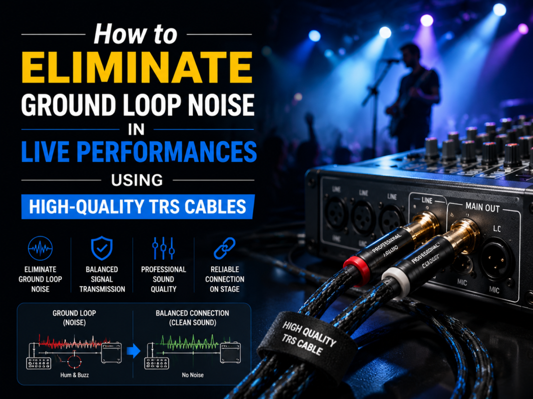
Balanced wiring can improve noise immunity, but it does not correct a damaged cable, incorrect pinout, ground loop, overloaded input, or incompatible interface. For system-level hum problems, see the separate guide to TRS cable ground-loop noise.
Using the same 1/4-inch plug does not make the cables equivalent.
| Characteristic | Instrument cable | Speaker cable |
|---|---|---|
| Typical signal | Low-level, often high-impedance instrument signal | Amplifier output driving a passive speaker |
| Common construction | One signal conductor plus shield | Two current-carrying conductors, often without an overall shield |
| Main priorities | Capacitance, shielding, handling noise, flexibility | Conductor resistance, current, length, connector capability, mechanical durability |
| Substitution risk | May overheat or lose excessive voltage if used for a speaker load | May pick up noise or alter instrument response if used as an instrument lead |
Follow the amplifier, speaker, and instrument manufacturer requirements. Never select a cable only because the connectors fit.
Conductor material, cross-sectional area, strand construction, length, and termination affect resistance and flexibility. “Oxygen-free copper” is often used as a marketing term, but measurable conductor resistance, cable capacitance, geometry, durability, and application fit are more useful design inputs.
Cable capacitance can affect high-frequency response when a passive high-impedance instrument drives a long cable. The result depends on the instrument pickup, source impedance, cable capacitance per unit length, total length, and input impedance. There is no single cable length that is optimal for every instrument system.
Braided, served, foil, or combination shields have different flexibility, coverage, termination, and durability characteristics. The best option depends on movement, connector design, noise environment, service life, and manufacturing method.
The jacket protects the cable from handling, abrasion, stage traffic, temperature, oils, and cleaning exposure. Connector boots, clamps, chuck strain relief, overmolds, and bend geometry help prevent conductor fatigue at the plug entry.
Nickel, tin, gold, and other contact finishes have application-specific tradeoffs. Plating should be selected from the connector manufacturer’s mating system, environment, expected use, and maintenance requirements. Gold color alone is not proof of plating thickness, conductivity, durability, or cable quality.
| Plug style | Useful for | Design checks |
|---|---|---|
| Straight plug | Patch bays, rack equipment, general studio connections | Rear clearance, cable support, accidental lever force |
| Right-angle plug | Guitars, pedals, compact panels, side-mounted jacks | Exit direction, enclosure interference, rotation, strain relief |
| Low-profile or pancake plug | Dense pedalboards and limited-clearance installations | Connector diameter, shielding, assembly space and repairability |
| Overmolded plug | Repeat production and sealed or tamper-resistant assemblies | Material compatibility, flex transition, tooling and validation |
Connector orientation should be included in the drawing. A right-angle plug that points the wrong way can make an otherwise correct cable unusable.
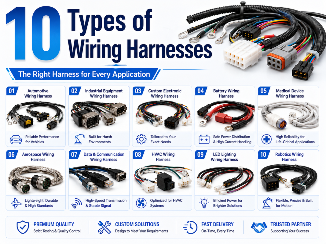
For custom breakouts or mixed connector assemblies, review media cable harness options and the broader custom cable assembly range.
| Symptom | Possible causes | Checks |
|---|---|---|
| Hum or buzz | Ground loop, unbalanced routing, damaged shield, equipment grounding issue | Test the system layout, power and grounding; use a known-good cable and correct balanced interface |
| Signal only on one headphone side | Wrong plug type, broken conductor, dirty jack, adapter or source issue | Confirm TRS stereo pinout, test another source and cable, inspect connectors |
| Weak, thin, or phase-affected sound | Balanced/unbalanced mismatch, incorrect insert wiring, partial contact, adapter error | Verify equipment pinout and cable assignment; inspect plug seating |
| Crackling during movement | Broken strands, weak solder joint, worn jack, poor strain relief, contamination | Move each cable section carefully, inspect the connector and test a known-good cable |
| No signal | Open conductor, wrong output or input, muted equipment, incompatible pinout | Check equipment settings, continuity, pinout and connector seating |
| Speaker cable becomes warm | Excessive resistance, undersized conductors, damaged connector, overload | Stop use and verify the amplifier, load, cable construction, length and connector system |
FireWire and MIDI are different digital interfaces sometimes found in the same audio system. Use the guides to FireWire cable types and MIDI cable selection when troubleshooting those connections.
No universal capacitance, resistance, insertion loss, flex life, plating thickness, or test voltage applies to every 1/4-inch audio cable. Limits should come from the equipment requirements, cable and connector datasheets, approved drawing, and project test plan.
A custom cable development process helps confirm pinout and construction before production, while a prototype cable assembly can verify fit, handling, noise, and application behavior. The cable and wire harness quality guide provides a general inspection framework.
Yes. The connector family commonly called 1/4-inch is also described as 6.35 mm. Always verify TS, TRS, or TRRS contact count and the equipment pinout.
TS has two contacts and commonly carries unbalanced mono audio or a speaker/control circuit. TRS has three contacts and can carry balanced mono, unbalanced stereo, insert send/return, headphone, or control signals.
No. TRS describes three connector contacts. Balanced operation requires compatible balanced output and input circuits plus the correct cable wiring. TRS is also widely used for stereo headphones and insert cables.
Do not assume it is suitable. Guitar cable is normally shielded and intended for low-level instrument signals, while passive speaker cable needs conductors sized for amplifier current and cable length. Follow the amplifier and speaker requirements.
Only if the equipment supports the intended wiring. A standard guitar output is commonly unbalanced TS. A TRS plug may be used for active switching, stereo instruments, balanced equipment, or special circuits, so the manual and pinout must be checked.
Many mixer inserts use a TRS connector carrying send and return on separate contacts, often broken out to two TS connectors. The tip and ring assignment varies by equipment, so use the mixer documentation.
There is no universal maximum. Acceptable length depends on balanced or unbalanced operation, source impedance, signal level, cable capacitance, shielding, routing, noise environment, and equipment requirements.
Send the equipment models, interface labels, TS/TRS/TRRS pinout, required length, cable application, connector orientation, environment, and test requirements through the WIRES contact page. This allows the cable to be specified without assuming that every 1/4-inch plug or TRS connection serves the same function.
 English English
 Vietnamese
 Indonesian
 Arabic
 Spanish