Quick answer: Use an industrial wire harness when one assembly must route multiple circuits through a compact piece of equipment. Use a cable assembly when a protected cable must connect two devices, panels, or enclosures. The best choice depends on current, voltage, signal type, bend radius, vibration, temperature, fluids, ingress protection, and the applicable product standards.
This guide explains the practical differences between wire harnesses and cable assemblies, the information required for specification, common industrial failure risks, and the production controls that help prevent wiring defects.
| Selection factor | Wire harness | Cable assembly |
|---|---|---|
| Typical structure | Multiple wires, branches, terminals, connectors, and protective components | One cable or cable bundle terminated at two or more ends |
| Typical application | Internal equipment routing and multi-circuit distribution | Point-to-point connections between equipment, panels, or enclosures |
| Routing needs | Useful when circuits split into several branches or follow complex paths | Useful when a continuous, controlled cable route is preferred |
| Protection options | Tape, braid, conduit, sleeving, clips, seals, and local strain relief | Outer jacket, shielding, backshells, overmolding, and sealed connectors |
| Design priority | Space utilization, branch layout, identification, and installation efficiency | Flexibility, environmental protection, transmission performance, and end-to-end durability |
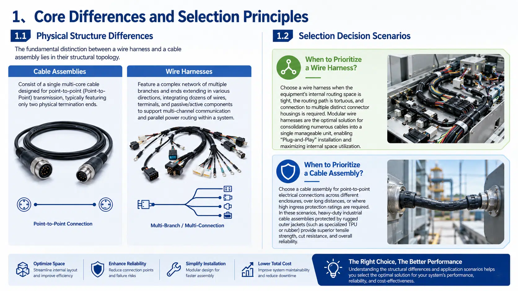
A wire harness and a cable assembly can use similar conductors and connectors, but they solve different routing problems. A harness organizes several independent circuits into a single installable assembly. A cable assembly normally provides a defined connection path between two points. The distinction matters because it affects connector selection, strain relief, shielding, testing, packaging, and installation time.
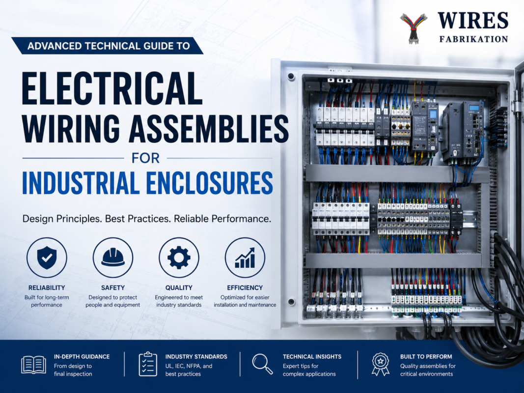
A wire harness is usually the better choice when several circuits must share a defined route inside a machine, control cabinet, vehicle, or industrial module. Branches can terminate at different connector housings, sensors, actuators, power devices, or grounding points. The harness can also include labels, clips, conduits, braided sleeving, and branch protection that simplify installation.
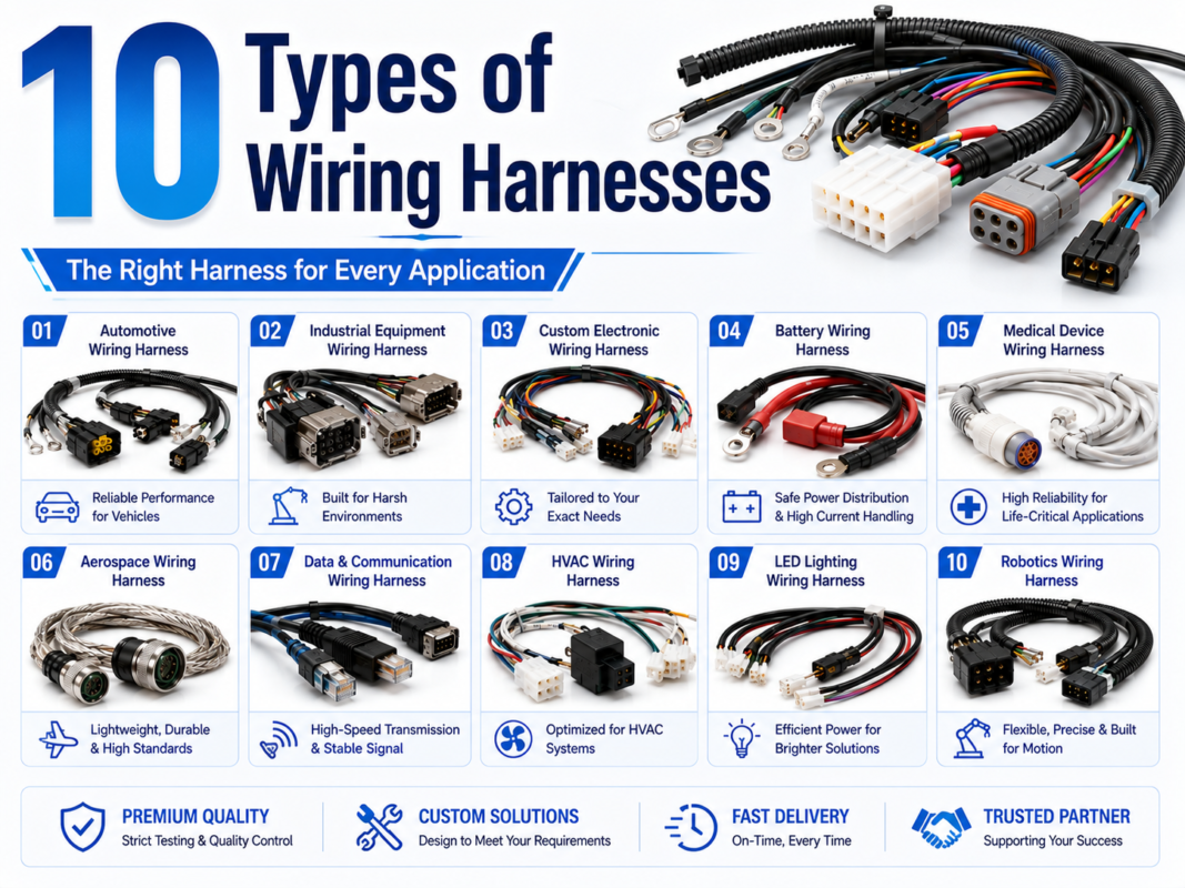
For tight equipment layouts, the harness drawing should show branch lengths, connector orientation, breakout locations, service loops, bend limits, and attachment points. These details help the manufacturer build a repeatable assembly instead of relying on an installer to sort and route loose wires in the field. See the overview of wiring harness types and applications when comparing a new design with an existing product architecture.
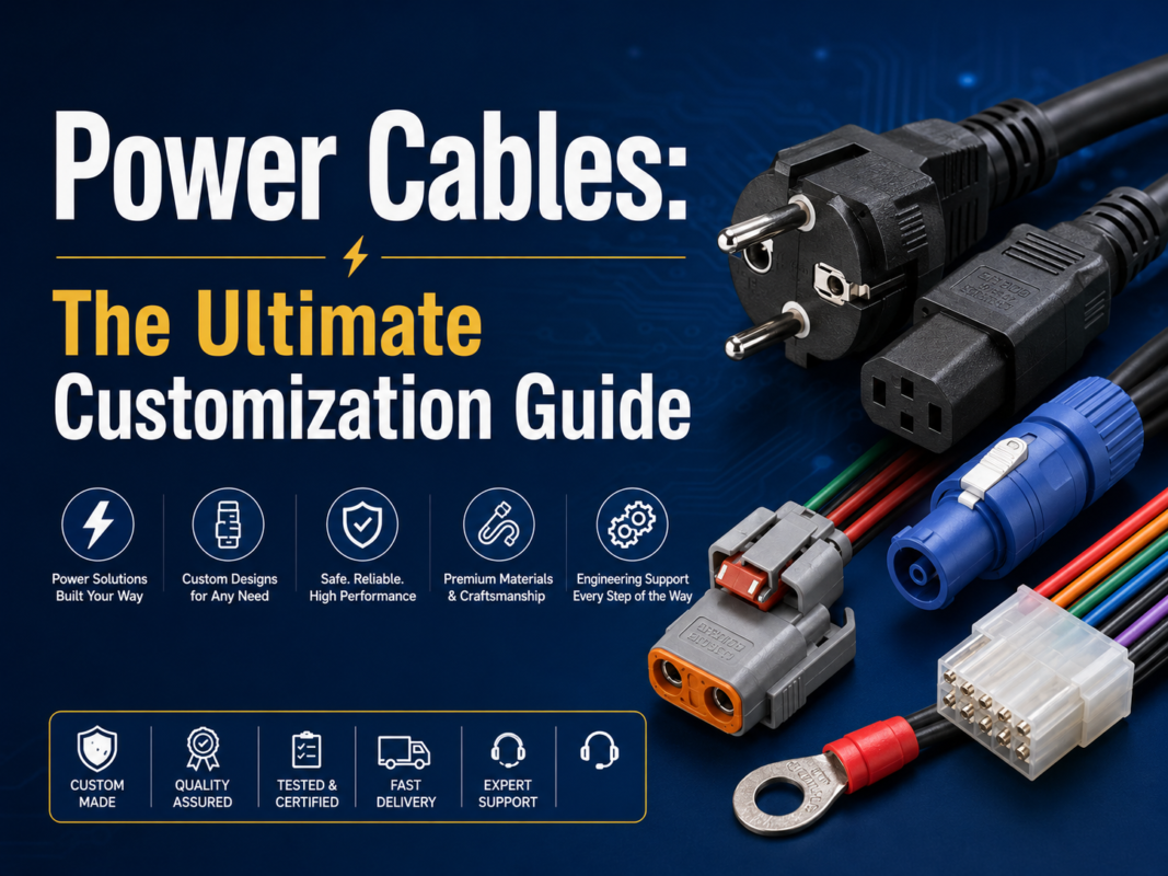
A cable assembly is often preferable when a single protected cable must run between two devices or enclosures. The outer jacket can provide continuous abrasion protection, and the cable construction can be selected for shielding, flexibility, chemical resistance, high temperature, or repeated motion.
For outdoor equipment, robotics, test systems, and machine interfaces, pay close attention to connector sealing, backshell design, strain relief, jacket compatibility, and bend radius. A cable assembly should be designed as a complete system: the connector, cable, termination, overmold or backshell, and mounting method all contribute to reliability.
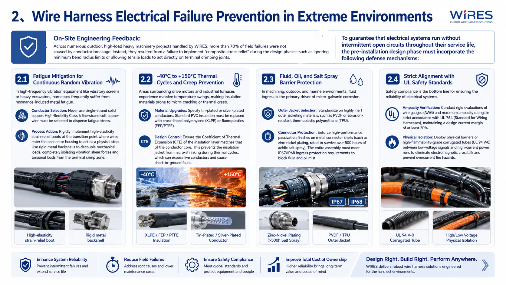
Industrial harnesses can fail even when the conductor size is correct. The most common design gaps involve mechanical loading, moisture paths, material compatibility, and connector termination. The design review should consider the complete load path from the equipment mounting point through the harness protection and into the terminal or connector.
Vibration can loosen terminals, damage insulation, fatigue conductors, and transfer excessive force into a crimp. Use flexible stranded conductors where movement is expected, provide controlled strain relief at connector exits, and prevent the harness from rubbing against sharp edges or unsupported brackets.
For moving assemblies, document the bend radius, travel length, movement speed, cycle expectation, and cable carrier or guide arrangement. The correct bend radius must come from the cable and connector design data; a generic multiplier should not replace supplier validation.
Temperature changes can harden, soften, shrink, or crack insulation and seals. Select the conductor insulation, jacket, grommet, sleeve, and connector seal as a compatible material system. Verify the continuous temperature rating, short-term exposure rating, flex performance, and chemical resistance for the actual operating environment.
Where oil, coolant, fuel, cleaning fluid, or salt spray is present, specify the exposure in the drawing and ask for material compatibility evidence. Do not assume that a higher IP rating alone proves resistance to every fluid or chemical.
Water can enter through connector interfaces, damaged jackets, unsealed transitions, and capillary paths inside stranded conductors. Waterproof designs may require sealed connector systems, correctly installed wire seals, backshells, overmolding, drip loops, and controlled test methods. The target IP rating should be stated for the assembled product and its installation condition.
For a sealed point-to-point connection, compare the design with a purpose-built waterproof cable assembly. The connector, cable, and sealing process should be qualified together rather than selected independently.
High-current and low-level signal circuits may need physical separation, shielding, twisted pairs, drain wires, or a defined grounding strategy. The right arrangement depends on the signal type, switching frequency, current, system architecture, and EMC requirements. Use the electrical schematic and applicable equipment standard to define the separation and termination rules.
A repeatable manufacturing process starts with complete design data. A manufacturer should be able to identify every wire, terminal, connector, branch, protection component, and test requirement before production begins. A custom wire harness process review can identify unclear dimensions, inaccessible fasteners, incorrect terminal selections, and routing conflicts before they become production problems.
The manufacturing package should include a controlled schematic, wire list, connector pinout, bill of materials, assembly drawing, inspection points, and revision history. Work instructions should define wire preparation, stripping length, terminal orientation, crimp settings, insertion checks, branch protection, labeling, and final inspection.
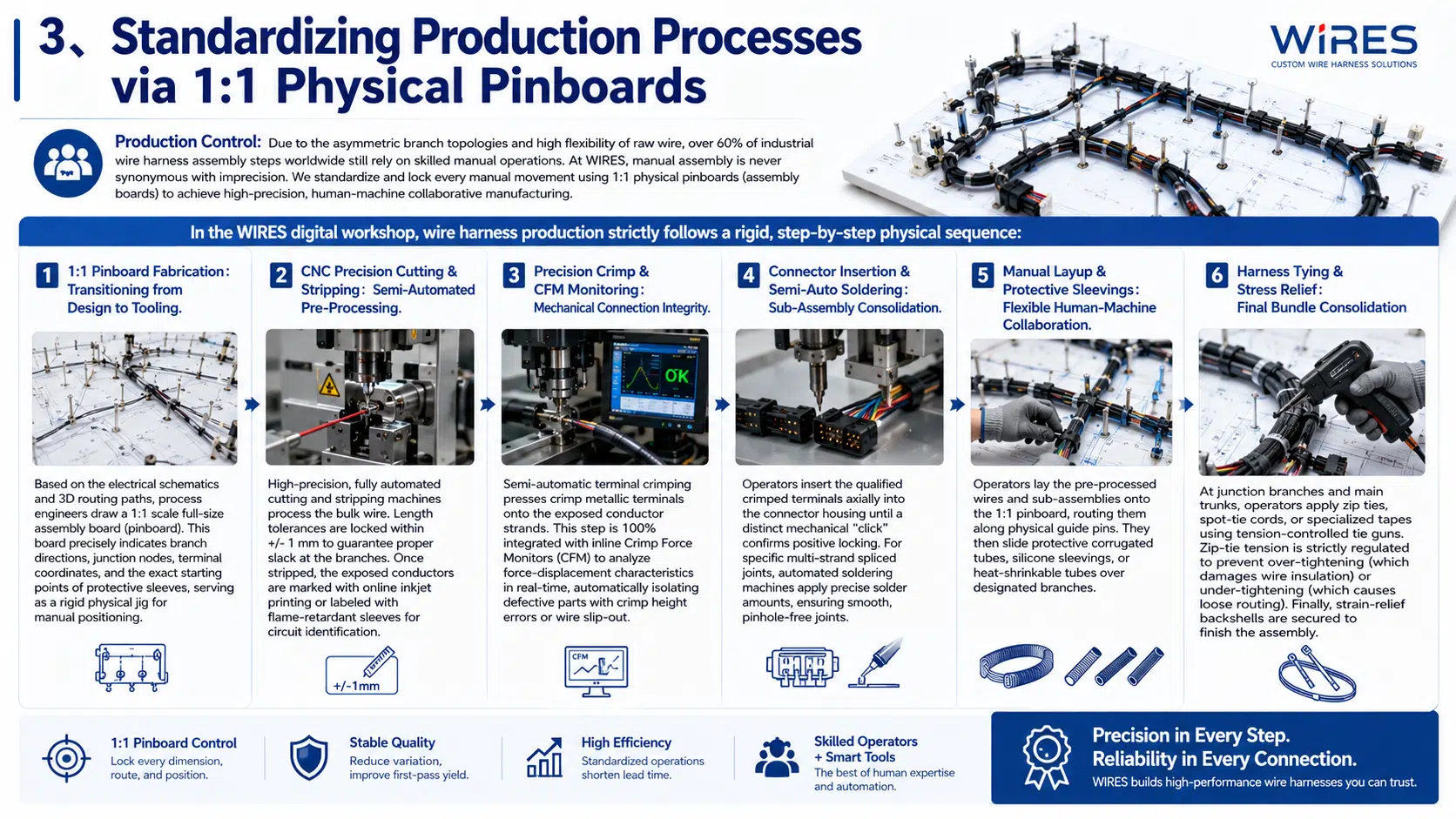
Automatic or semi-automatic equipment can improve repeatability for wire cutting and stripping, but the process still needs setup verification. Confirm cut length, strip length, conductor condition, insulation damage, circuit identification, and traceability at the start of a production run and whenever material or tooling changes.
A reliable crimp depends on the correct terminal, conductor, applicator, tooling, strip length, crimp height, and pull-force requirement. Use the terminal supplier’s application specification and the relevant workmanship standard as the acceptance basis. Where appropriate, monitor crimp force and retain setup records.
After crimping, verify terminal position, locking lance engagement, seal placement, and connector cavity assignment. A continuity test cannot detect every mechanical assembly error, so visual and dimensional checks remain important.
For branched harnesses, a 1:1 assembly board or equivalent fixture helps control branch length, connector orientation, breakout position, protective sleeve placement, and bundle shape. The fixture should reflect the approved drawing and be updated when the design revision changes.
Install conduit, braid, tape, heat-shrink, clips, labels, and strain relief according to the drawing. Ties and clamps should secure the route without cutting into insulation or restricting the required flex. Final inspection should check the complete assembly against the drawing before electrical testing and packing.
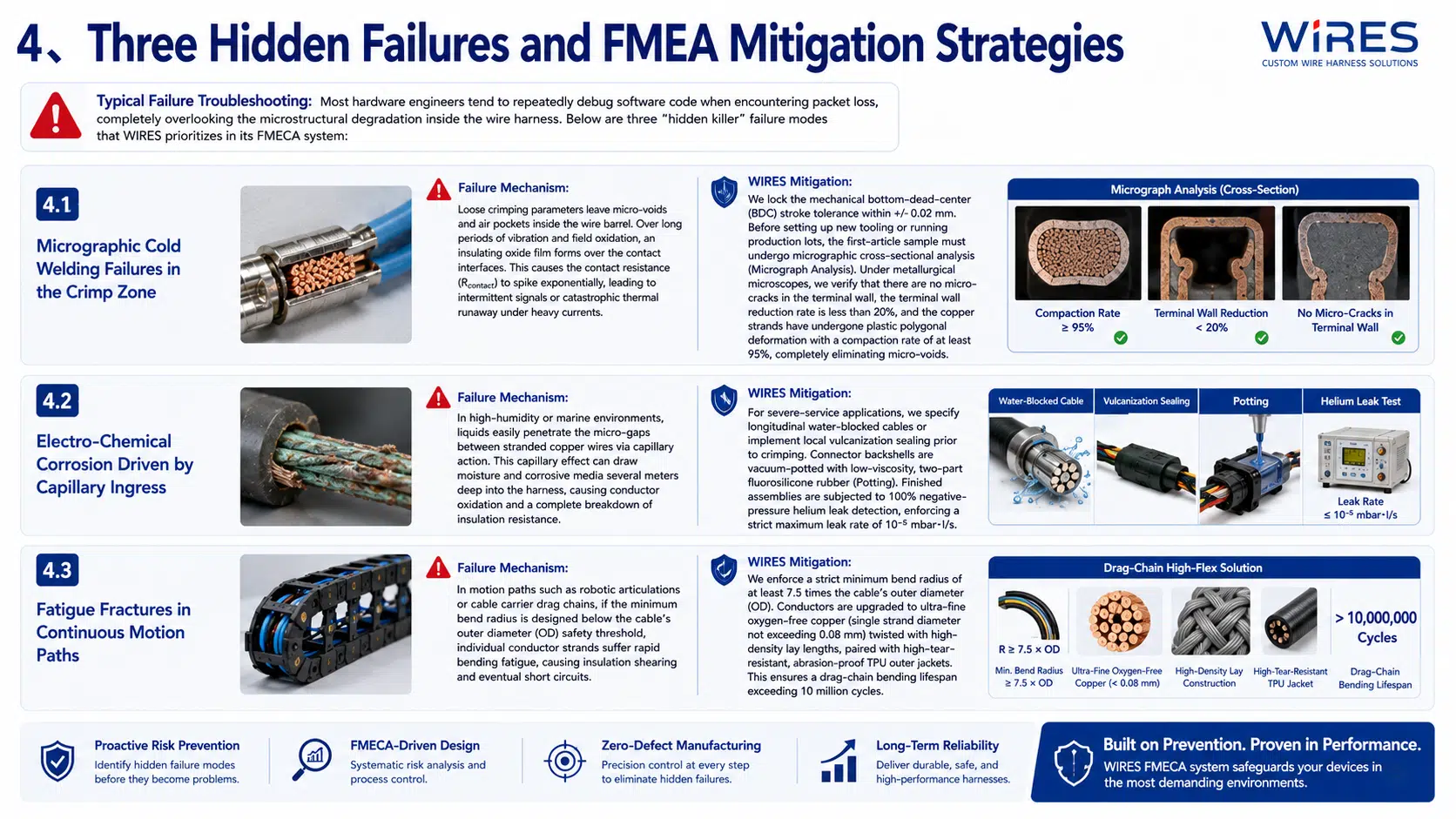
Incorrect crimp height, damaged strands, excessive insulation in the barrel, or an unsuitable terminal can create a weak or high-resistance connection. Prevent these defects with controlled tooling, first-piece approval, crimp-height measurement, pull testing where required, and visual inspection of the conductor brush and terminal wings.
Corrosion often begins at an unsealed connector interface, damaged jacket, or exposed transition. The design should specify seal compatibility, connector assembly steps, drain or venting requirements, and the environmental test method. When the application is severe, consider sealed splices, overmolded transitions, or water-blocking construction based on the cable supplier’s data.
Repeated movement can break conductor strands and wear through insulation. Define the motion profile, bend radius, flex direction, support spacing, and cycle requirement before selecting a cable. A drag-chain cable, robotic cable, or other continuous-flex construction may be necessary; a standard fixed-installation wire is not automatically suitable for motion.
A harness may pass a basic continuity check and still be wrong if a connector cavity, terminal, seal, or circuit label is incorrect. Use controlled pinout data, barcode or visual identification where practical, connector cavity checks, and a test program that matches the approved schematic. Substitutions should require engineering approval and documented equivalence.
Quality requirements should be defined before quotation and repeated on the manufacturing drawing or purchase specification. A suitable inspection plan may include:
IPC/WHMA-A-620 is commonly used as a workmanship reference for cable and wire harness assemblies. The required class, acceptance criteria, and test coverage should be agreed by the customer and manufacturer for the application. UL, automotive, aerospace, medical, railway, and other sector requirements may add material, process, or documentation obligations.
For a structured review of inspection and testing topics, see the WIRES guide to wire harness quality control. A manufacturer should also explain which tests are performed on every assembly, which are sampling tests, and which require a separate validation plan.
Clear input data produces a more accurate quotation and reduces engineering changes. Send the following whenever available:
When the design is still developing, send the available information and identify what is provisional. The engineering team can then flag missing requirements before tooling or production begins. WIRES also supports prototype cable assembly requests for early fit, routing, and test validation.
A wire harness combines multiple wires and branches into an organized assembly for internal routing or circuit distribution. A cable assembly usually uses one cable or cable bundle to connect defined points, often with stronger continuous jacketing or sealing.
Yes, if the conductors, insulation, protection, connectors, seals, and mounting method are selected for the outdoor environment. Specify temperature, UV, water, salt, vibration, and chemical exposure rather than relying on the label “outdoor rated.”
Most projects start with visual inspection and continuity or pinout testing. Depending on the risk and applicable standard, the plan may add insulation resistance, dielectric withstand, crimp verification, dimensional inspection, shielding checks, ingress testing, vibration, flex, or temperature validation.
Include the schematic reference, wire and terminal list, connector pinout, branch dimensions, connector orientation, labels, protective materials, bend and strain-relief requirements, tolerances, test requirements, packaging, and revision control.
Yes. Provide the available schematic, connector information, layout, electrical requirements, and environmental conditions. The review can identify missing specifications, routing conflicts, connector or material risks, and opportunities to improve manufacturability before a final quotation.
Request a Custom Wire Harness or Cable Assembly Review
Send your schematic, connector list, drawing, 3D routing sketch, or sample requirement to the WIRES engineering team. We can review the application, identify missing specifications, and recommend a manufacturable wire harness or cable assembly configuration.
 English English
 Vietnamese
 Indonesian
 Arabic
 Spanish