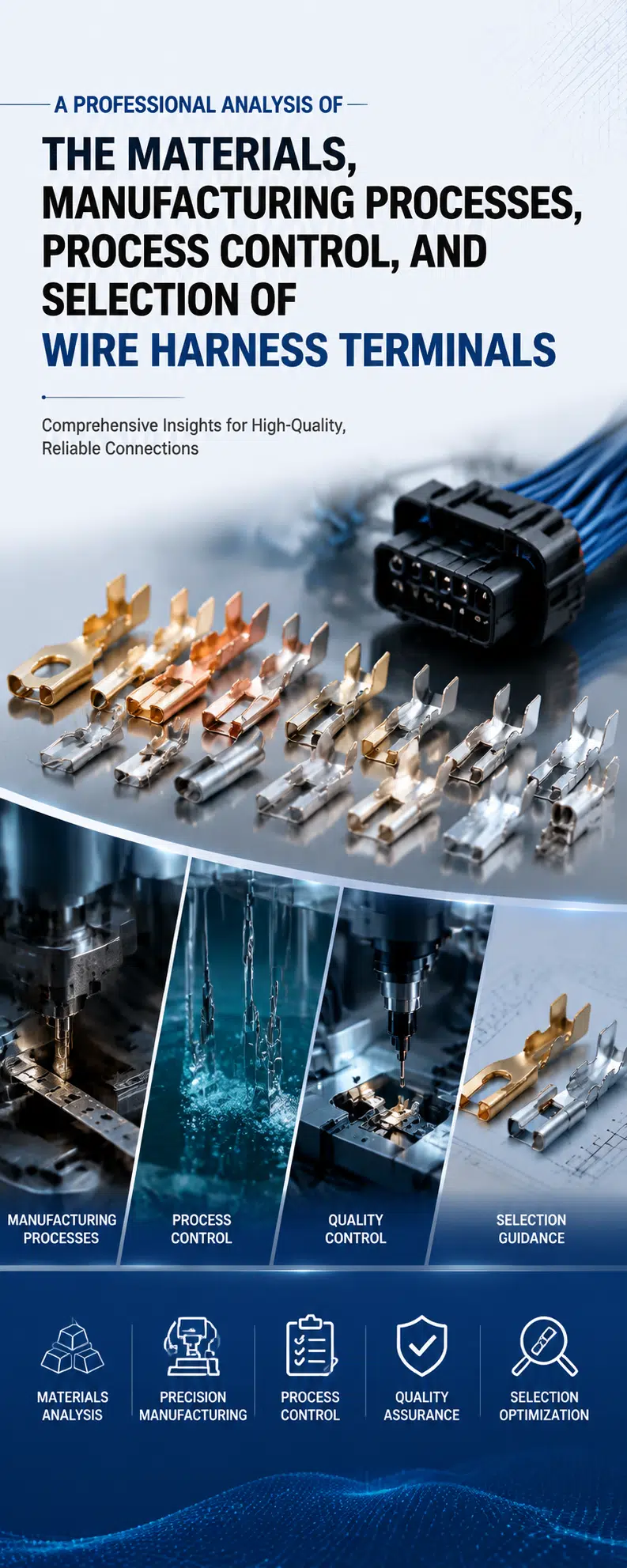
Quick answer: Select a wire harness terminal as part of a complete connection system. Match the terminal to the connector housing, mating contact, conductor size, insulation diameter, electrical load, environment, plating, crimp tooling, and validation requirements. A terminal that fits physically can still fail if its material, plating, or crimp geometry is wrong.
This guide explains terminal materials, plating, manufacturing, crimp control, inspection, failure modes, and the information needed for a reliable production release.
A wire harness terminal is the conductive contact attached to a wire and retained inside a connector housing or used as a standalone lug, tab, receptacle, splice, or ring terminal. It creates both an electrical path and a mechanical interface.
Most open-barrel connector terminals include a contact area, conductor crimp, insulation support, locking lance, and carrier-cutoff area. Each feature has a different function and inspection requirement. The terminal, wire, housing, mating contact, seal, and tooling should be treated as one approved system.
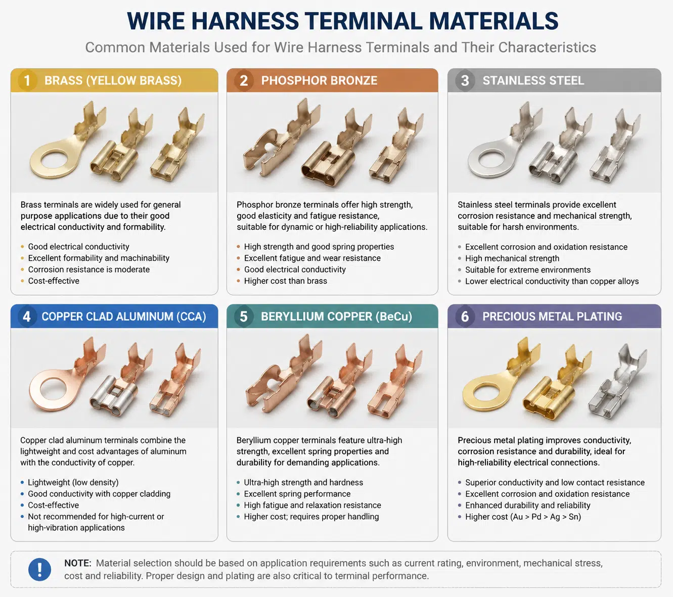
| Material family | Typical advantages | Important limitations | Common use |
|---|---|---|---|
| Brass | Good formability, useful strength, broad availability, economical | Spring performance and stress relaxation may be lower than some other copper alloys | General tabs, receptacles, and cost-sensitive connections |
| Phosphor bronze | Good spring properties, fatigue resistance, and corrosion resistance | Material grade and temper must match the contact design | Signal and power contacts requiring reliable normal force |
| Beryllium copper | High strength, spring performance, and fatigue resistance after proper heat treatment | Higher cost, controlled processing, and material-handling requirements | Small or demanding spring contacts where the design justifies it |
| High-conductivity copper alloys | Improved electrical conductivity for selected power-contact designs | Mechanical strength and stress relaxation must still meet the contact requirement | Higher-current terminals and bus connections |
| Steel or stainless components | High mechanical strength and corrosion resistance in selected parts | Lower electrical conductivity than copper alloys | Retention springs, support parts, or special terminals rather than the primary current path |
Material names alone do not define performance. Alloy composition, temper, thickness, contact geometry, heat treatment, and plating all influence conductivity, insertion force, retention, and long-term contact pressure.
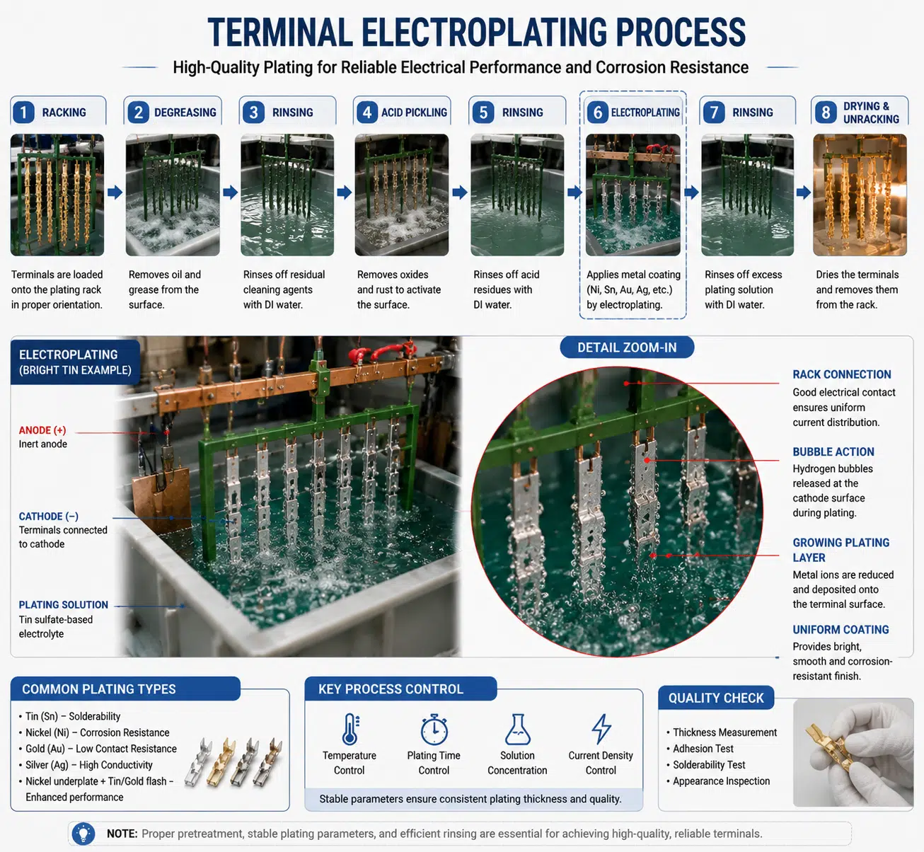
Plating protects the base metal and controls the contact interface. The most expensive finish is not automatically the best choice.
| Finish | Typical strengths | Selection notes |
|---|---|---|
| Tin | Economical, solderable, widely used for power and signal contacts | Consider fretting, mating force, temperature, and compatibility with the mating finish |
| Silver | High conductivity and useful performance in selected higher-current contacts | Tarnish, sulfur exposure, lubrication, and contact force require consideration |
| Gold | Stable low-level signal contact and corrosion resistance when correctly specified | Thickness, underplate, wear, porosity, and mating cycles affect performance and cost |
| Nickel | Common as an underplate or for elevated-temperature and wear-related applications | It is not a universal replacement for tin, silver, or gold contact finishes |
Avoid mismatched plating systems unless they have been evaluated for the environment and mating life. Contact lubricant, fretting motion, humidity, temperature, current level, and the number of mating cycles can change the preferred finish.
Most connector terminals are produced from copper-alloy strip using progressive dies. Stamping creates the contact geometry, locking features, conductor wings, insulation wings, and carrier. Critical dimensions depend on die condition, strip properties, press setup, and inspection.
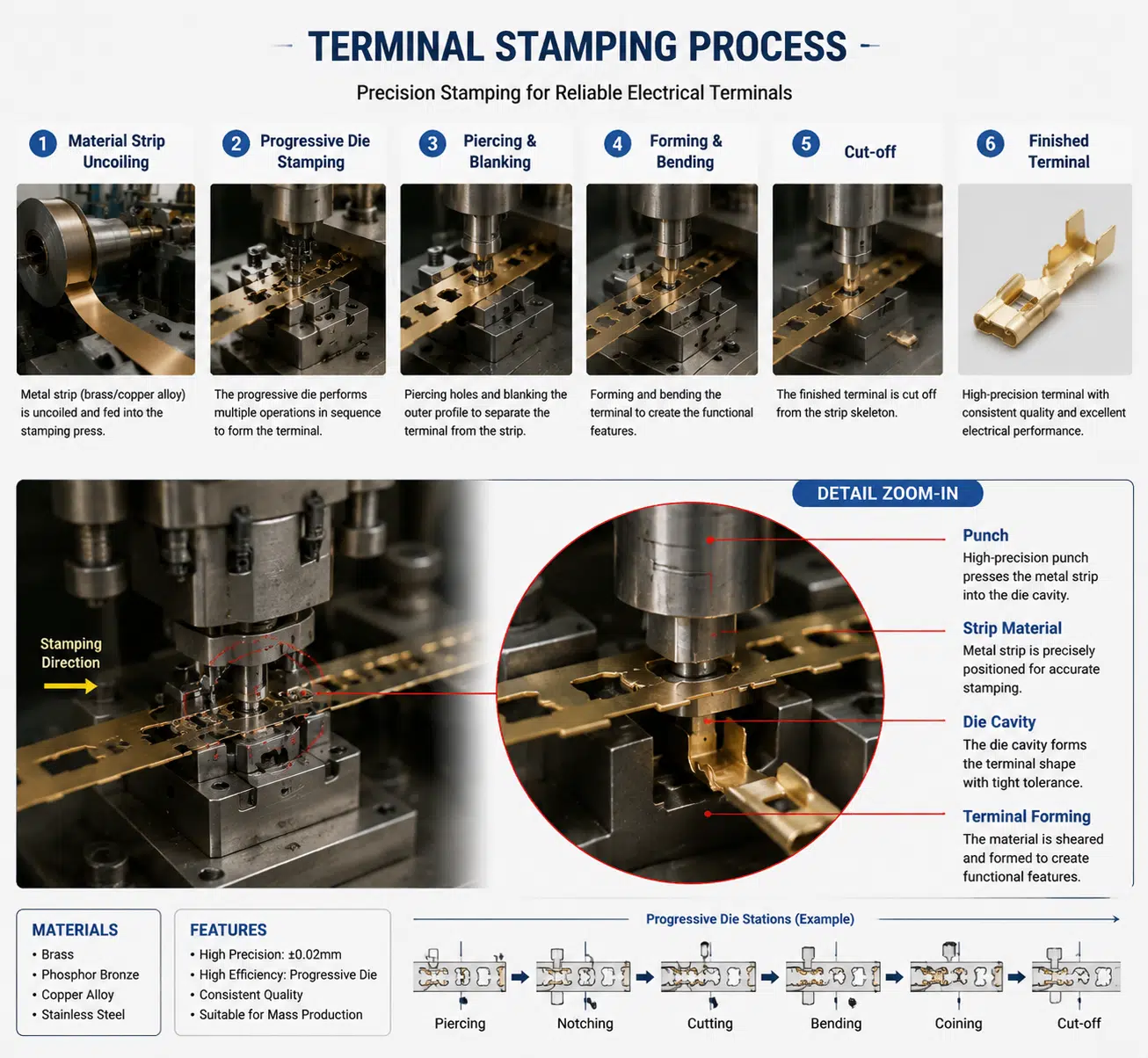
Depending on the alloy and design, terminals may require cleaning, stress relief, heat treatment, underplating, and final contact plating. Plating thickness and location should follow the terminal drawing or manufacturer specification.
Injection molding normally produces the connector housing, seals, strain-relief features, or overmolded cable body. It is related to the complete connector assembly but is not the metal-terminal stamping process itself.
A crimp forms a controlled mechanical and electrical connection by compressing the terminal barrel around the conductor. The required geometry is specific to the terminal, wire, applicator, and setup. There is no universal crimp height, compression ratio, or pull-force limit for all wire harness terminals.
Standards such as IEC 60352-2 or USCAR-21 may be referenced by a project, but the applicable revision, test method, sample plan, and acceptance limits must be stated in the engineering requirements.
| Selection area | Information required |
|---|---|
| Electrical | Continuous and peak current, voltage, signal level, allowable voltage drop, temperature rise, fault conditions |
| Wire | Conductor size, strand count, conductor material, plating, insulation material, outside diameter |
| Interface | Housing, mating contact, tab thickness, pin size, circuit count, keying, terminal position assurance |
| Mechanical | Insertion, extraction, retention, vibration, flexing, strain relief, mating cycles |
| Environment | Temperature, humidity, salt, fluids, dust, water, corrosion, cleaning agents |
| Manufacturing | Applicator, press, hand tool, setup specification, gauges, inspection equipment, spare-tool strategy |
| Quality | Drawing revision, approved source, sampling plan, test records, traceability, change control |
A controlled wire harness manufacturing process should define the inputs, setup checks, inspection frequency, reaction plan, and records for each terminal and wire combination.
The wire harness quality-control page provides a broader view of inspection and testing.
| Method | What it checks | Important note |
|---|---|---|
| Visual inspection | Strand damage, bellmouth, brush, cutoff, insulation position, wing closure, terminal damage | Use terminal-specific acceptance criteria and suitable magnification |
| Crimp-height measurement | Conductor-crimp compression and setup consistency | Use the specified measurement location and limit |
| Pull test | Mechanical strength of the wire-to-terminal connection | Method, pull rate, wire size, and acceptance limit must be defined |
| Crimp cross-section | Strand distribution, compression, voids, symmetry, cracks, and support | Useful for setup validation and process investigation |
| Voltage-drop or resistance test | Electrical performance of the termination path | Define current, measurement points, temperature, and limits |
| Environmental or vibration test | Performance under project-specific exposure | Usually qualification or validation rather than a generic production test |
| Failure | Common cause | Corrective direction |
|---|---|---|
| High resistance or heating | Wrong terminal, under-crimp, contamination, overload, poor mating contact | Verify part numbers, crimp setup, electrical load, and mating interface |
| Broken strands | Damaged stripping process, over-crimp, incorrect tooling, flexing near the barrel | Review strip quality, tooling alignment, crimp dimensions, and strain relief |
| Terminal backs out | Damaged locking lance, incomplete insertion, wrong housing, wire load | Check terminal compatibility, insertion, retention, and harness routing |
| Fretting or corrosion | Micro-motion, unsuitable plating, humidity, fluids, low contact force | Review finish, connector retention, sealing, lubricant, and environment |
| Housing or seal damage | Wrong terminal orientation, oversized insulation, incorrect seal, excessive insertion force | Confirm the complete terminal-housing-wire-seal combination |
| Intermittent open circuit | Conductor fatigue, weak crimp, terminal movement, damaged mating contact | Use mechanical support, correct crimping, and system-level validation |
Terminal selection varies by equipment and installation zone. An automotive wiring harness may prioritize vibration, temperature, sealing, and approved-source requirements. Medical cable harnesses may require risk controls, cleaning compatibility, and documented configuration. Agricultural machinery harnesses often face dust, moisture, vibration, and service exposure.
Do not transfer a terminal specification from one industry to another without reviewing the electrical load, environment, connector, standards, and customer requirements.
A prototype wire harness can confirm terminal insertion, fit, routing, strain relief, and manufacturability before production release.
There is no universal best material. Select the alloy and temper from the electrical, spring, temperature, fatigue, forming, corrosion, and cost requirements of the contact design.
No. Gold is useful for selected low-level signal and corrosion-sensitive interfaces, but thickness, underplate, wear, mating finish, contact force, and cost matter. Tin or silver may be more suitable for other applications.
Use the application specification for the exact terminal, wire, and tooling. A value from another terminal or wire size should not be reused.
No. Pull testing checks mechanical strength but does not fully evaluate strand damage, crimp geometry, electrical resistance, terminal seating, or long-term environmental performance.
Not unless the approved design and process require it. Adding solder can change flexibility, wicking, fatigue behavior, and terminal insertion.
Common causes include the wrong terminal, damaged locking lance, incorrect orientation, incomplete insertion, housing damage, or external wire load.
It is useful for applicator setup, validation, periodic process review, new wire-terminal combinations, and failure analysis when required by the quality plan.
Only after engineering approval. Compare material, plating, dimensions, retention, mating interface, wire range, tooling, ratings, and validation evidence.
Provide the terminal and housing part numbers, wire specification, application environment, crimp criteria, inspection plan, and quantity range. Contact WIRES for a wire harness terminal and assembly review.
 English English
 Vietnamese
 Indonesian
 Arabic
 Spanish