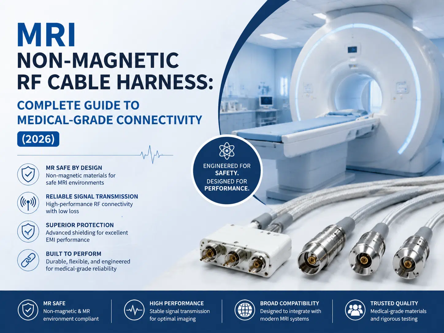
Quick answer: An MRI non-magnetic RF cable harness connects RF coils, interface electronics, sensors, or supporting modules while limiting magnetic interaction and preserving the required signal path. The assembly must be designed for the specific scanner, field strength, RF frequency, connector interface, routing, cleaning environment, and OEM verification plan.
“Non-magnetic” should not be treated as a marketing label. Materials, components, tools, and finished assemblies need project-specific evaluation for magnetic compatibility and electrical performance.
An MRI RF cable harness is an application-specific cable assembly used within or near magnetic resonance imaging equipment. Depending on the design, it may carry RF signals, low-level sensor signals, control circuits, or power between coils, patient-interface equipment, electronics modules, and system enclosures.
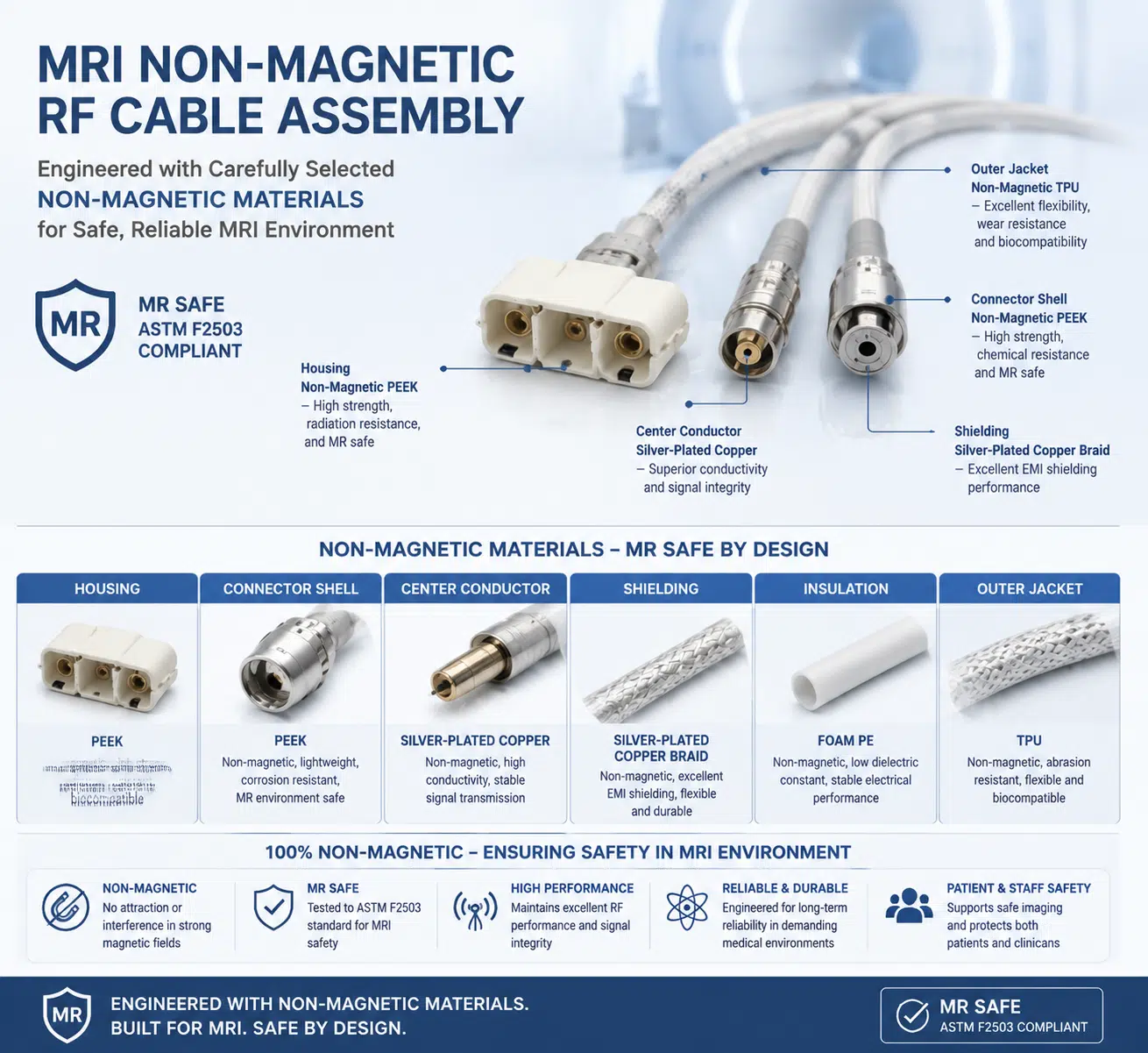
The harness may combine coaxial cable, twisted pairs, shielding, non-ferromagnetic connectors, strain relief, labels, and protective jackets. For related product capabilities, see medical cable harnesses and RF cable assemblies.
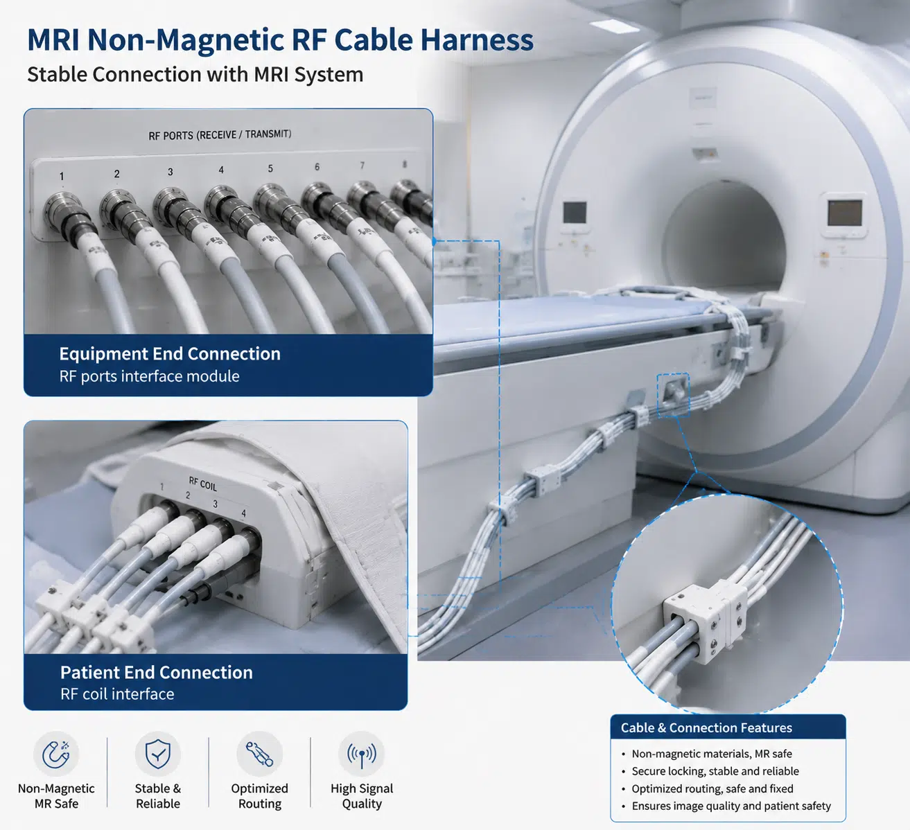
MRI equipment operates with a strong static magnetic field, switched gradient fields, and RF energy. Common clinical systems include 1.5 T and 3 T scanners, while other field strengths are also used. Compatibility must be defined by the scanner OEM and the location of the cable within the system.
Ferromagnetic components can experience force or torque and may disturb the local magnetic field. Conductive structures can also interact with gradient or RF fields, depending on their geometry and placement. Therefore, material selection is only one part of the design; routing, loop area, shielding, grounding, connectors, and verification are equally important.
| Requirement area | Questions to define | Design impact |
|---|---|---|
| Scanner environment | Field strength, cable location, bore proximity, restricted zones, OEM rules | Controls magnetic compatibility and installation constraints |
| RF interface | Frequency range, characteristic impedance, allowable loss, power level, connector type | Determines cable construction, connector transitions, and verification |
| EMC | Shielding, grounding, common-mode current, emissions, susceptibility | Controls braid, foil, backshell, bonding, and routing decisions |
| Mechanical | Length, flexing, bend radius, pull load, patient-table motion, strain relief | Influences conductor construction, jacket, support, and service life |
| Materials | Magnetic limits, cleaning agents, temperature, flame behavior, biocompatibility scope | Guides conductor, plating, connector, jacket, and marking choices |
| Verification | Electrical tests, RF tests, magnetic evaluation, cleaning validation, documentation | Defines qualification and production acceptance evidence |
RF performance depends on the complete signal path. Cable impedance, attenuation, connector transitions, shield continuity, grounding, routing, and bend geometry should be evaluated together.
RF measurements should use the project’s approved method and limits. A generic shielding percentage or loss value should not be applied to every MRI harness.
Potential material choices include copper or copper-alloy conductors, selected platings, polymer insulation, elastomeric jackets, engineered plastics, and non-ferromagnetic connector hardware. Suitability depends on the exact location and function.
A cable can meet its RF specification on the bench and still perform poorly after installation if it is bent, pinched, unsupported, or repeatedly flexed outside its design limits.

A controlled custom cable assembly process should begin with the scanner interface, drawing, BOM, material restrictions, and verification plan. Prototypes can be used to confirm fit, routing, mating access, and RF behavior before production release.
| Activity | Typical purpose |
|---|---|
| Material and component review | Confirm approved part numbers, magnetic restrictions, and substitution controls |
| Visual and dimensional inspection | Verify workmanship, lengths, labels, connector orientation, and strain relief |
| Continuity and wiring test | Detect opens, shorts, and pinout errors |
| RF test | Evaluate impedance-related behavior, insertion loss, return loss, or shield continuity when specified |
| Mechanical checks | Assess retention, pull, flexing, or routing features defined by the drawing |
| Magnetic compatibility evaluation | Confirm suitability using the OEM-approved method and installation location |
| Cleaning or environmental validation | Assess resistance to specified cleaning agents, temperature, humidity, or other exposures |
Qualification tests and production acceptance tests are not the same. The project plan should state which tests apply to the design, first article, lot, or every assembly. Review the wire harness quality-control overview for related inspection concepts.
| Risk | Possible effect | Recommended response |
|---|---|---|
| Unverified metal component | Magnetic interaction or image disturbance | Review every component and use the OEM-approved evaluation method |
| Poor RF transition | Reflection, added loss, or unstable signal path | Control connector geometry, termination, and assembly-level RF tests |
| Shield discontinuity | EMI coupling or common-mode current | Define shield termination and grounding as part of the complete system |
| Excessive bend or pull | Changed impedance, conductor damage, or connector failure | Define routing, support, bend, and strain-relief requirements |
| Uncontrolled substitution | Different magnetic, chemical, or electrical behavior | Use approved part numbers and formal change control |
No. Conductive metals are needed for electrical and RF performance. The requirement is to control magnetic behavior and system interaction using approved materials and a defined evaluation method.
Not automatically. Field strength is only one factor. The scanner model, RF interface, cable location, routing, connectors, materials, and OEM approval all matter.
Use the impedance specified by the coil or equipment interface. Confirm the complete assembly, including connectors and transitions, against the approved RF test plan.
Only if its materials, construction, RF performance, routing, and magnetic compatibility meet the system requirements. A commercial cable description alone is not sufficient.
Define the frequency range, assembly configuration, termination, test method, and acceptance limit. Shield coverage alone does not describe complete assembly performance.
Provide the drawing, pinout, scanner interface, field strength, RF requirements, connectors, routing, material restrictions, cleaning environment, tests, documentation, and quantity range.
No. The cable is one component within a validated medical imaging system. Performance and safety depend on the complete equipment design, installation, risk management, and regulatory controls.
Prepare the scanner interface, RF requirements, magnetic restrictions, drawing, routing, verification plan, and documentation needs. Contact WIRES for an MRI RF cable harness requirements review.
 English English
 Vietnamese
 Indonesian
 Arabic
 Spanish