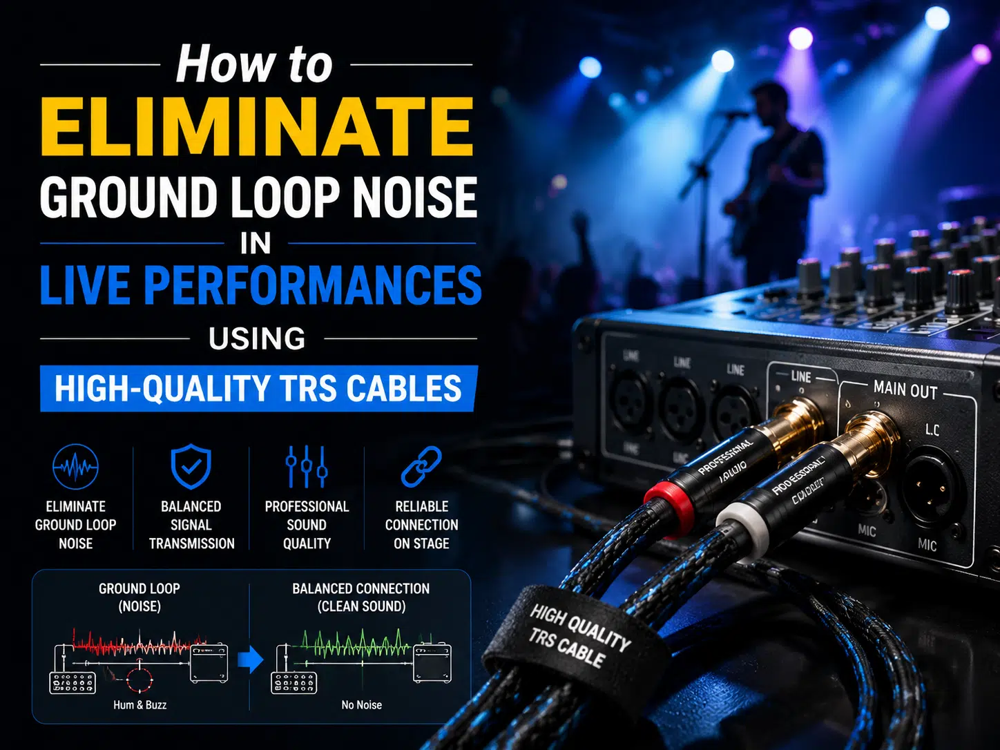
TRS cable ground loop noise is usually a system-level grounding problem, not proof that one cable is defective. Hum often appears when two connected devices reference ground through more than one path. A correctly wired balanced TRS connection can reject common-mode interference, but only when both devices provide compatible balanced inputs and outputs. Diagnose the complete signal and power path before replacing equipment.
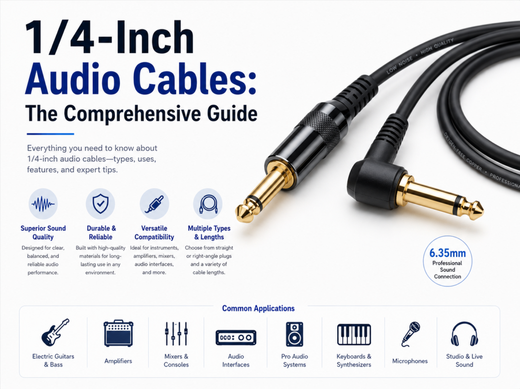
A TRS plug can carry balanced mono audio, unbalanced stereo audio, an insert send/return, or a control signal. If the wiring function is unclear, first review the 1/4-inch TS and TRS cable selection guide.
A ground loop exists when connected equipment has multiple conductive paths between ground references. Small voltage differences can drive current through cable shields or signal grounds. That current may enter the audio path as a steady 50/60 Hz hum, related harmonics, buzz, clicks, or noise that changes when equipment is connected.
The audible result depends on the equipment topology, power distribution, cable wiring, shield termination, gain structure, nearby electromagnetic fields, and the condition of the connectors. This is why a cable swap may appear to solve the problem even when the underlying cause is elsewhere.
| Observed symptom | Likely area to inspect | Useful first check |
|---|---|---|
| Hum begins when a second device is connected | Multiple ground paths | Mute the system and add one signal connection at a time |
| Noise changes when a laptop charger is connected | Power supply or grounding path | Compare the approved operating configurations without defeating protective earth |
| Noise rises when the cable crosses power leads | Magnetic or electric coupling | Separate the signal route and cross power cables at roughly right angles where practical |
| Hum appears only on one channel | Cable, connector, or channel hardware | Swap one known-good item at a time and record what moves with the fault |
| Buzz changes when a connector is touched | Shield continuity or termination | Power down and inspect the plug, strain relief, solder joints, and shield connection |
Balanced audio normally uses two signal conductors with opposite polarity plus a shield or reference conductor. The receiving input rejects noise that is coupled similarly into both signal conductors. This benefit depends on the complete interface, not the connector shape alone.
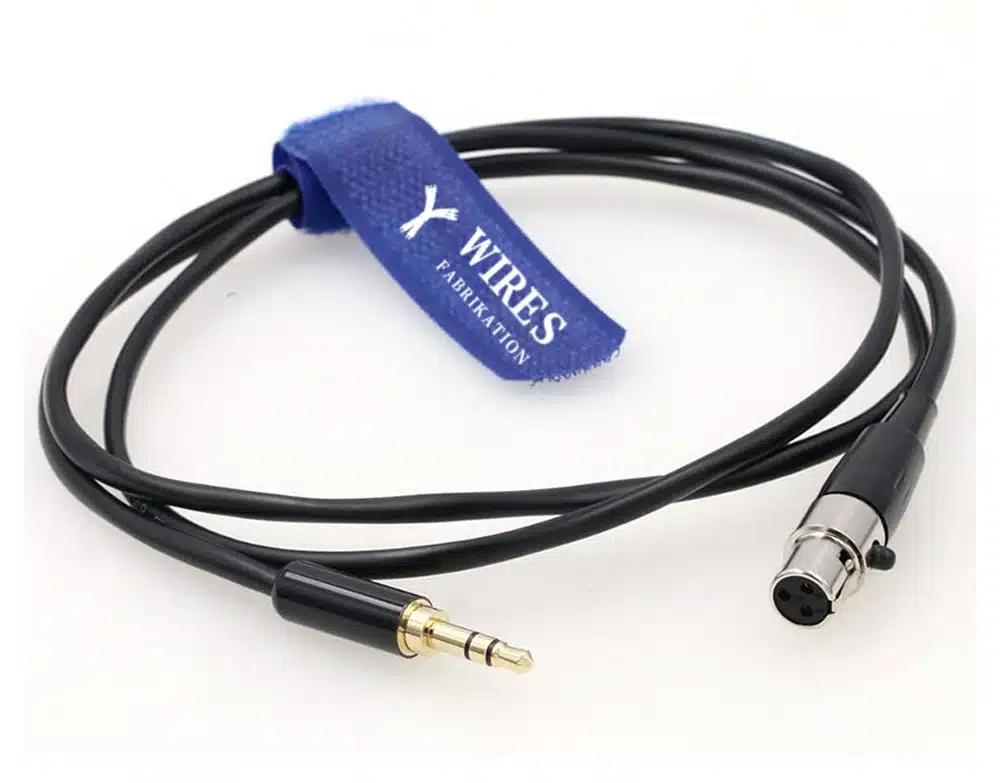
When a project needs a purpose-built interface, define the pinout, equipment at both ends, signal level, shielding method, cable length, flexing, and stage environment. The same documentation discipline used for a custom cable assembly specification also prevents audio wiring errors.
Work methodically. Randomly lifting grounds or changing several items at once can hide the cause and create a safety risk.
Confirm that the source output, cable wiring, adapters, patch panel, stage box, and receiving input all support the same balanced connection. One unbalanced section can reduce the noise-rejection benefit of the remaining path.
For integrated stage, broadcast, or entertainment wiring, review the complete media harness rather than treating each lead as an isolated part. Digital control lines also need correct pinouts and routing; the MIDI cable guide covers a related class of live-performance connections.
Where the venue design and applicable electrical rules allow, related audio equipment may benefit from a planned power distribution arrangement. This does not mean connecting excessive loads to one outlet or using unapproved adapters. A qualified electrician or venue technician should confirm circuit capacity, protective devices, grounding, and local-code requirements.
The routing and bonding principles used in industrial enclosure wiring are useful references, but stage power must still follow the venue’s electrical design and applicable regulations.
A suitable transformer isolator, isolation interface, or DI box can interrupt an unwanted signal-ground path while preserving the required audio connection. Select it for the actual signal type, impedance, level, frequency response, connector format, and phantom-power requirements. Do not treat a passive ground-lift switch as permission to disconnect mains safety earth.
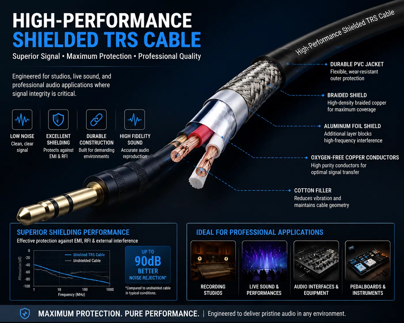
Keep microphone and line-level cables away from strong field sources. Avoid long parallel runs beside power cables. If signal and power paths must cross, a near-right-angle crossing can reduce coupling compared with a long parallel route. Shield design matters, but no single braid percentage or foil construction guarantees a quiet system in every installation.
For projects exposed to higher-frequency interference, the principles in the RF cable assembly guide help frame decisions about shielding, connector transitions, routing, and termination.
Choose the cable from the equipment requirements and mechanical environment, not from plating claims or a single marketing number.
| Selection factor | What to specify | Why it matters |
|---|---|---|
| Electrical function | Balanced mono, stereo, insert, control, or another defined pinout | TRS connectors can support different circuits |
| Conductor construction | Gauge, stranding, insulation, pair geometry, and approved material | Affects resistance, flexibility, termination, and handling |
| Shield system | Braid, serve, foil, drain wire, or combined construction | Affects flex life, coverage, termination, and interference control |
| Connector compatibility | Plug dimensions, contact arrangement, shell, strain relief, and mating jack | Prevents intermittent fit and incorrect wiring |
| Mechanical use | Touring, fixed rack, pedalboard, patch bay, studio, or installation | Defines flexing, abrasion, pull, and service requirements |
| Environment | Temperature, moisture, cleaning agents, traffic, and storage conditions | Guides jacket and protection choices |
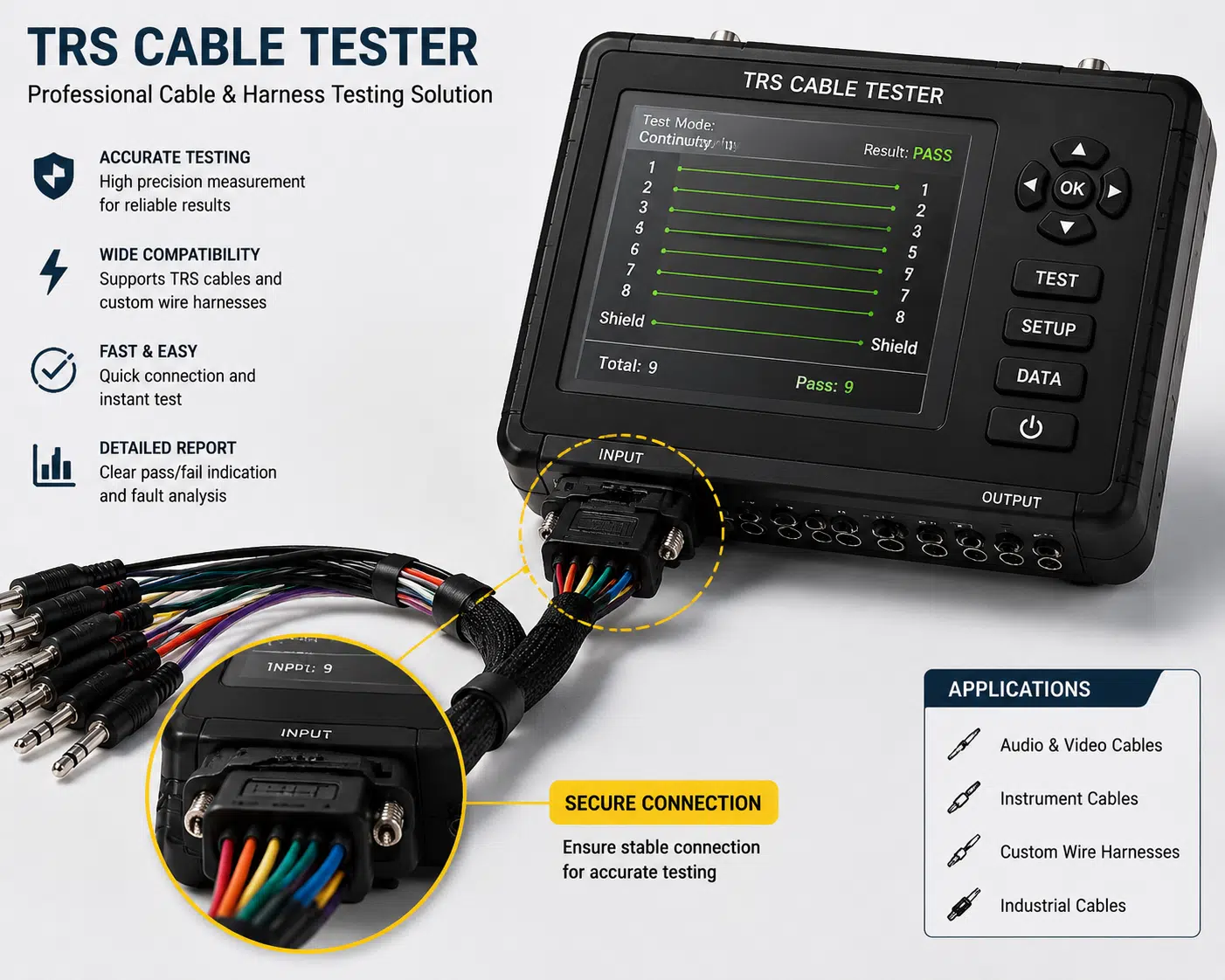
| Verification | Continuity, short-circuit check, pinout confirmation, visual inspection, and project-specific tests | Confirms the assembly matches the drawing and application |
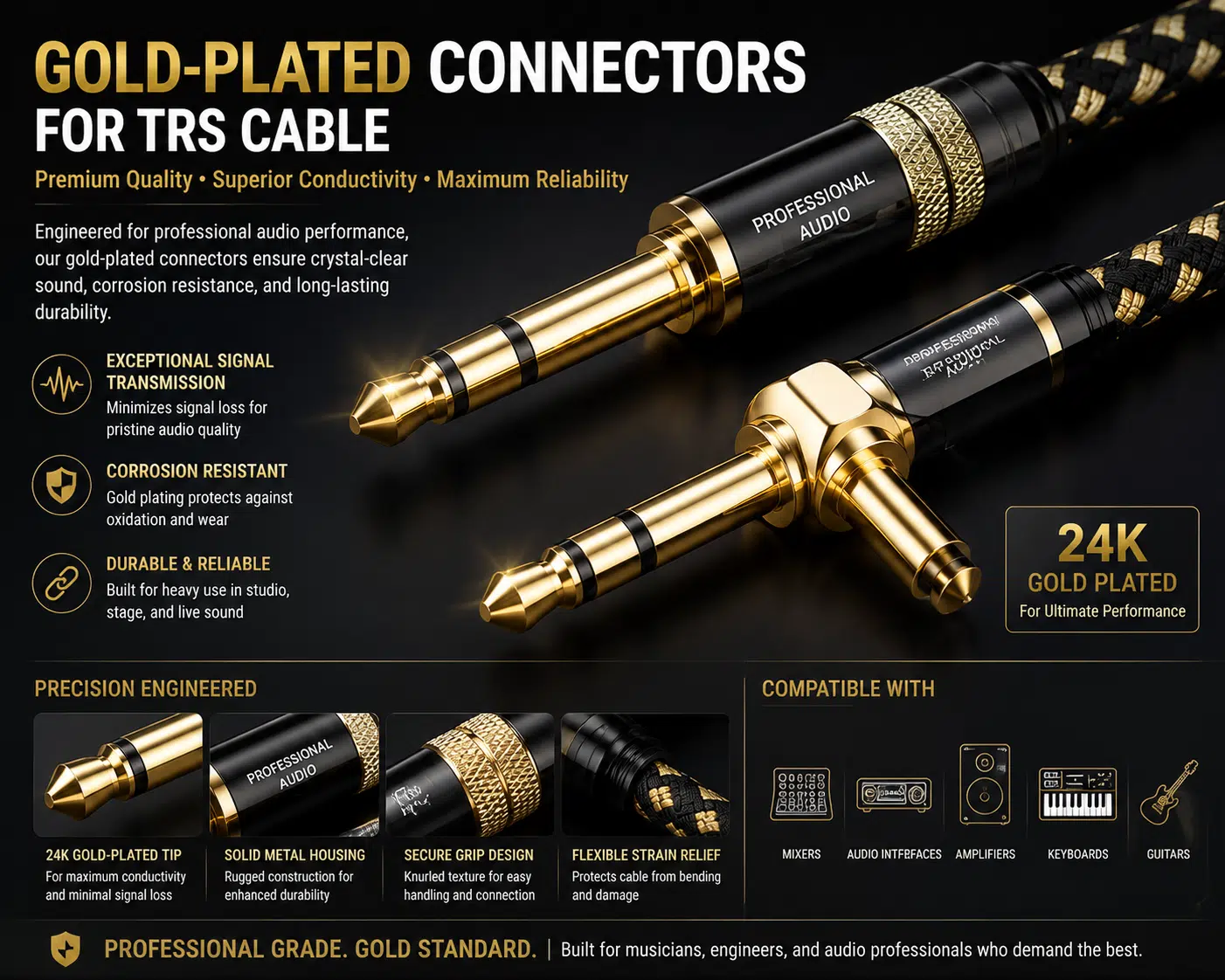
Plating can improve corrosion behavior and contact stability in a suitable connector system, but gold color, silver color, or a claimed purity value does not prove audio performance. The mating design, base material, plating process, cleanliness, contact force, soldering, strain relief, and handling all matter.
| Finding | Interpretation | Next action |
|---|---|---|
| Hum disappears when the signal cable is disconnected | The loop involves that signal path, but the cable may not be the root cause | Check both device grounds, interface type, adapters, and power sources |
| Hum remains with the source disconnected | The noise may originate later in the chain | Inspect the mixer channel, rack, amplifier, monitor, and local power |
| Noise follows one cable during a controlled swap | Cable wiring or termination is suspect | Quarantine, inspect, test, and repair or replace the cable |
| Noise follows one device | Device power supply, output circuit, or grounding may be involved | Check the manual and have the equipment serviced if required |
| Noise changes with lighting or motors | Coupled interference or shared power disturbance is possible | Review separation, power distribution, and venue electrical conditions |
| Isolation removes the hum | A signal-ground path was involved | Confirm the isolator is correctly rated and document the final configuration |
A useful request includes the equipment models, connector part numbers or dimensional requirements, pinout, balanced or unbalanced function, signal level, cable length, shield termination, jacket environment, bend and flex conditions, labeling, packaging, and acceptance tests.
Review the available custom cable assembly range, then use the customized development process to organize drawings and requirements. A prototype cable assembly can be evaluated in the actual equipment before production requirements are finalized. Acceptance criteria should follow a documented cable and wire harness quality plan, not an unsupported universal performance claim.
A TRS cable can complete one of the conductive paths involved in a ground loop, but the root cause is usually the relationship among connected equipment, power grounds, interface circuits, adapters, and shield terminations. Replacing the cable helps only when its wiring, shielding, connector, or routing is part of the problem.
No. Balanced wiring can reject common-mode interference, but it cannot correct every grounding fault, unbalanced interface, defective device, incorrect adapter, or poor power-distribution arrangement.
No. Do not defeat the protective-earth connection on mains-powered equipment. Use approved audio isolation methods and have venue power or grounding issues assessed by qualified personnel.
The charger can introduce another ground or noise path, but the exact behavior depends on the computer, power supply, audio interface, and venue wiring. Diagnose the complete connection and use approved isolation or interface equipment where required.
There is no universal answer for every audio interface. Follow the equipment manufacturer’s wiring guidance and the approved system design. Changing shield termination without understanding the circuit can worsen noise or compromise compatibility.
Plating mainly affects contact behavior and corrosion resistance within a specific connector design. It does not by itself guarantee lower hum, wider frequency response, or better sound quality.
Custom construction is useful when standard cables do not meet the required pinout, connector geometry, routing, flexibility, labeling, shielding, length, or verification needs. Provide the full system requirements so the cable can be reviewed as part of the signal path.
Effective TRS cable ground loop noise control starts with a safe, repeatable diagnosis. Verify the interface type, add connections one at a time, inspect power and routing, test known-good cables, and use correctly specified balanced or isolated interfaces. Do not rely on connector plating, shield percentage, or a single laboratory number as proof of stage performance.
For a project-specific cable review, send the equipment interfaces, pinout, cable length, operating environment, routing constraints, and acceptance requirements through the WIRES contact page.
 English English
 Vietnamese
 Indonesian
 Arabic
 Spanish