Quick answer: A custom power cable is designed around a defined voltage, continuous and peak current, cable length, allowable voltage drop, connector system, temperature, movement, fluids, installation method, and required safety or product standards. Wire gauge alone does not determine whether a cable is suitable.
The correct design balances electrical loss, conductor heating, insulation performance, connector temperature rise, mechanical protection, and manufacturability. This guide explains how to specify custom AC and DC power cables without relying on generic current charts or unverified performance claims. If the distinction between harnesses and jacketed cables is unclear, start with the wire harness vs. cable assembly comparison.
For related industrial configurations, review custom cable assembly options.
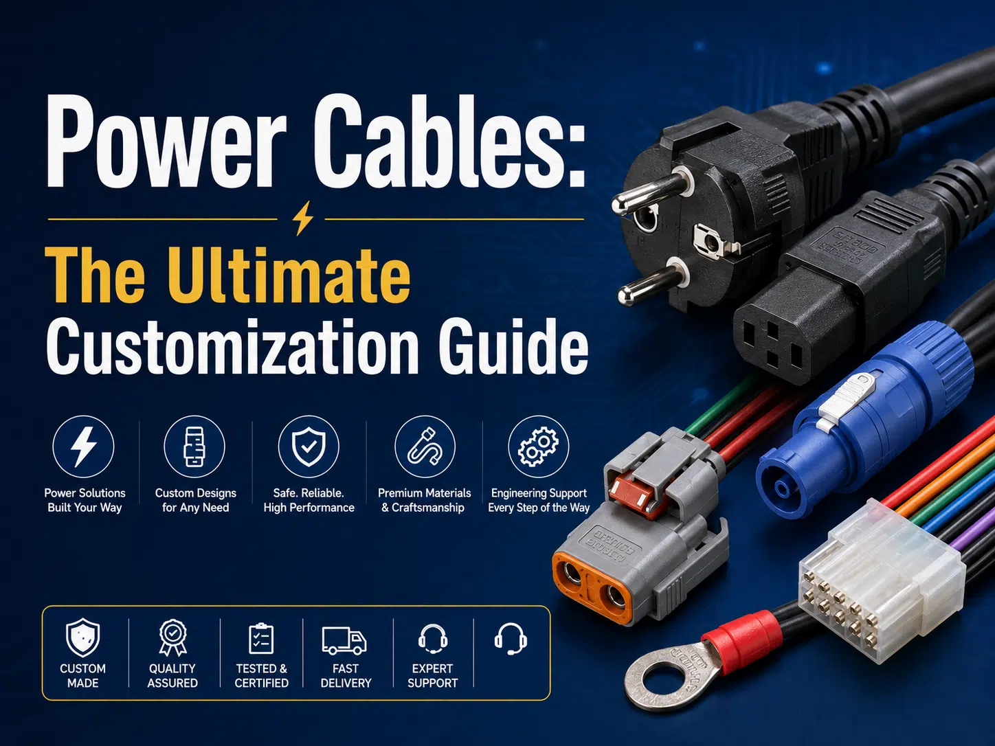
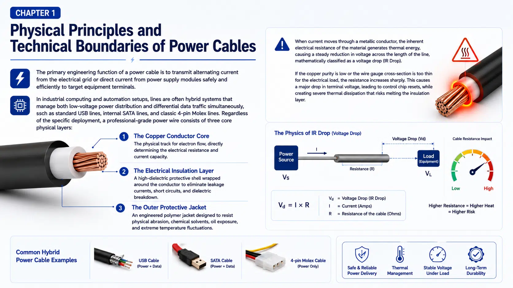
A custom power cable transfers electrical energy between a source and a load using conductors, insulation, terminals or contacts, connector housings, strain relief, and an optional outer jacket, shield, braid, conduit, or overmold. It can be a simple two-wire DC lead, an AC mains cord, a battery cable, an internal equipment assembly, a motor cable, or a hybrid assembly carrying both power and signals.
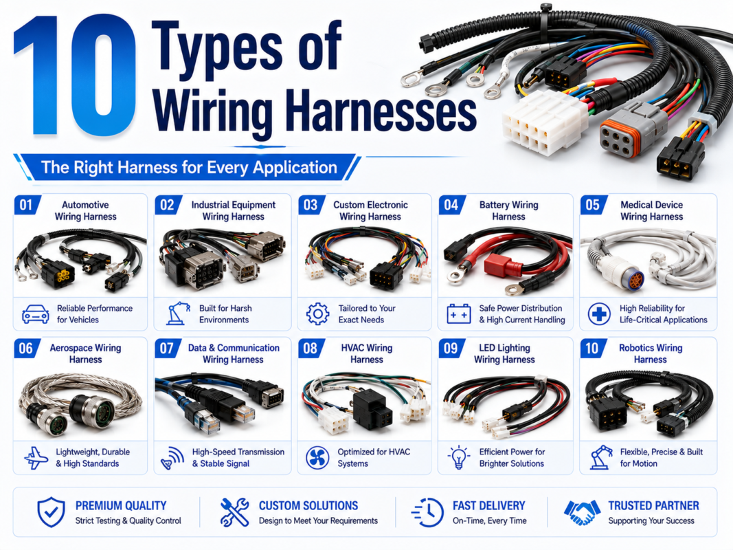
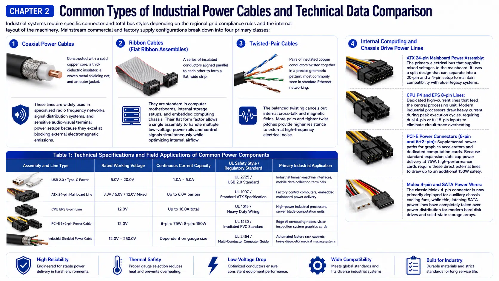
Coaxial cable, ribbon cable, and twisted-pair cable are construction formats, not automatically power-cable categories. They may carry power in a specific system, but their suitability depends on the interface specification, conductor size, insulation, connector, thermal limits, and protection. For assemblies with multiple branches, see common wire harness types and applications.
| Custom power cable type | Typical applications | Main design priorities | Key information to confirm |
|---|---|---|---|
| AC mains cord | Equipment input, appliances, instruments, power supplies | Regional plug, flexible cord, grounding, strain relief, safety approval | Country, voltage, frequency, load, inlet, cord standard, installation category |
| Low-voltage DC lead | Controls, sensors, displays, communications equipment | Polarity, voltage drop, connector retention, protection | Continuous and peak current, length, duty cycle, connector and fuse |
| High-current battery cable | Vehicles, energy storage, inverters, starter and charging circuits | Conductor area, terminal interface, heat, short-circuit protection | Current profile, cable length, ambient temperature, lug and fastener requirements |
| Internal equipment power assembly | Industrial PCs, servers, cabinets, embedded equipment | Pinout, airflow, connector temperature, routing, serviceability | Power-supply specification, mating connector, branch layout, enclosure limits |
| Motor and drive cable | Motors, variable-frequency drives, servos, robotics | EMC, flexing, insulation stress, grounding, oil resistance | Drive type, motor current, switching environment, shield termination, motion profile |
| Hybrid power-and-signal cable | Cameras, actuators, smart equipment, mobile systems | Noise coupling, thermal interaction, breakout design, connector pin assignment | Signal protocol, shielding, power load, separation, validation method |
| Outdoor or sealed power cable | Marine, solar, lighting, machinery, washdown equipment | Water, UV, temperature, chemicals, sealing, abrasion | Exposure conditions, ingress test, jacket material, connector configuration |
State the normal voltage, maximum operating voltage, transients, AC frequency where relevant, circuit category, grounding method, and required dielectric or insulation test. The connector, wire insulation, spacing, overmold, and finished assembly must all suit the voltage and environment.
A wire or connector voltage rating should be taken from the current manufacturer datasheet or applicable specification. Do not assume that a physically larger connector automatically has a higher usable voltage, especially in contaminated, wet, or low-pressure environments.
Continuous current controls steady heating, while startup, motor, charging, or pulse loads may create higher short-duration current. Specify the load profile and duration rather than providing only one maximum number. Connector contacts, terminals, splices, and conductors can have different thermal limits.
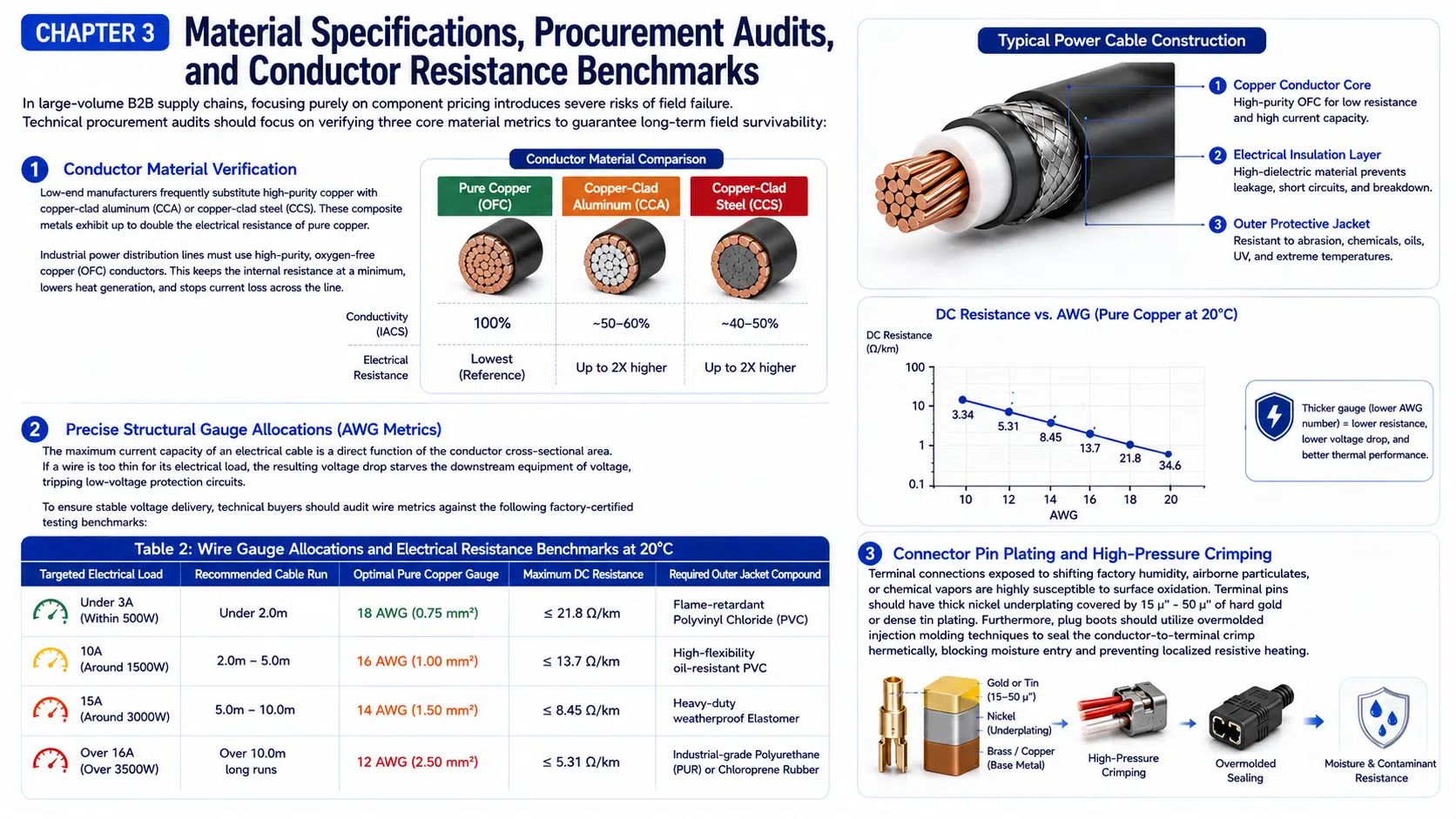
Ampacity depends on conductor material and area, insulation temperature class, ambient temperature, number of loaded conductors, bundling, ventilation, connector design, and installation method. Generic AWG charts are useful for preliminary screening but cannot replace the governing standard or project calculation.
For a simple DC circuit, voltage drop can be estimated with Vdrop = I x R. Resistive cable heating can be estimated with Ploss = I squared x R. Resistance must include the complete current path: outgoing and return conductors, terminals, contacts, splices, and other series connections.
Longer cables, smaller conductor area, higher current, elevated conductor temperature, and additional connections increase voltage drop. AC systems may also require consideration of phase, power factor, reactance, and installation rules. The acceptable drop must come from the load specification and system design, not a universal percentage.
For vehicle power distribution, the car electrical wiring harness guide explains how duty cycle, routing, terminals, and circuit protection affect conductor selection.
| Material or construction | Useful characteristics | Important limitations | Evidence to request |
|---|---|---|---|
| Bare copper conductor | Common electrical conductor with broad terminal compatibility | Stranding, temper, and surface condition affect flexibility and processing | Conductor standard, strand construction, resistance data, supplier datasheet |
| Tinned copper conductor | Can improve solderability and corrosion resistance in selected environments | Does not make the complete cable waterproof or marine-approved | Plating specification, conductor construction, environmental requirement |
| PVC insulation or jacket | Widely available and configurable for many fixed or moderate-flex applications | Performance varies substantially by compound | Temperature, voltage, flame, oil, flexibility, and regulatory data |
| XLPE or cross-linked insulation | Useful where heat, abrasion, or reduced wall thickness is required | Exact properties depend on the cable specification and compound | Applicable wire standard, aging and environmental test data |
| PUR or TPE jacket | Often selected for flexing, abrasion, oil, or industrial environments | Not every formulation has the same flame, chemical, or temperature performance | Named fluids, motion profile, flame requirement, supplier datasheet |
| Silicone or rubber construction | Can provide flexibility and temperature performance in suitable designs | May require special abrasion protection, termination, or cleaning controls | Application-specific mechanical and environmental test results |
| Fluoropolymer insulation | Used for compact, chemical-resistant, or elevated-temperature applications | Material choice, processing, cost, and termination require review | Exact polymer, wire specification, handling and test requirements |
“Oxygen-free copper” is often used as a marketing label, but cable selection should rely on measurable conductor resistance, cross-sectional area, strand construction, material specification, and application evidence. Copper-clad aluminum or other composite conductors should not be substituted for specified copper without engineering approval.
The power interface includes the contact, terminal, housing, seal, secondary lock, backshell, strain relief, mating connector, PCB connection, and protective device. The lowest-rated element can limit the complete system.
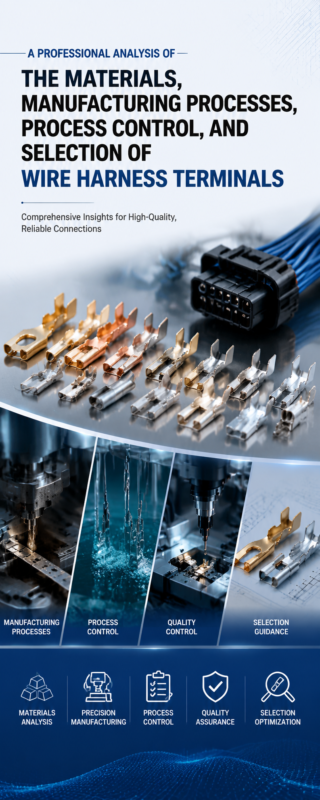
Review wire harness terminal materials and crimp selection before approving a terminal system. For compact low-voltage equipment, the JST connector guide explains why the housing, crimp terminal, header, wire range, and tooling must be matched.
Shielding is not required for every power cable. It may be needed near variable-frequency drives, switching converters, sensitive sensors, RF equipment, or when a product EMC plan requires it. The shield material, coverage, termination, grounding, and connector backshell should be designed as a complete system.
A shield that is poorly terminated can provide limited benefit or create unintended current paths. Motor and drive systems may have manufacturer-specific rules for shield continuity, protective earth, bonding, and cable routing. Follow the drive, motor, and equipment specifications.
When power and data share one assembly, separate the circuits according to voltage, heat, noise, and safety needs. Define twisted pairs, coax, controlled impedance, drain wires, shield termination, breakout length, and connector pin layout. The related industrial wire harness guide covers routing and protection in machinery.
| Environment | Typical risk | Design options | Verification input |
|---|---|---|---|
| Repeated flexing or torsion | Conductor fatigue, shield breakage, jacket cracking | Fine-stranded conductors, flex jacket, controlled bend radius, strain relief | Travel, speed, acceleration, bend radius, torsion, temperature, cycle target |
| Oil or chemicals | Swelling, softening, cracking, label or overmold damage | Compatible jacket, seals, markers, adhesives, and overmold materials | Named fluids, concentration, temperature, exposure time, acceptance criteria |
| Water or washdown | Corrosion, leakage, capillary ingress | Sealed connectors, overmolding, adhesive heat shrink, routing and drainage | Water pressure or depth, duration, temperature, mating condition |
| Heat or cold | Insulation aging, stiffness, seal damage, contact relaxation | Suitable wire, jacket, terminals, seals, heat barriers, routing | Normal and abnormal temperatures, dwell time, cycling profile |
| Vibration and impact | Connector separation, terminal wear, conductor damage | Positive locking, clamps, strain relief, protective sleeving | Equipment profile, mounting method, test axes, duration, inspection criteria |
| Outdoor UV exposure | Jacket cracking, fading, reduced mechanical strength | UV-rated jacket and protection appropriate to installation | Installation location, expected exposure, cable datasheet or test method |
An IP code under IEC 60529 applies to the tested enclosure or connector configuration and conditions; it is not a universal waterproof claim for a finished cable. See waterproof cable assembly design options for sealing, overmolding, and ingress-test planning.
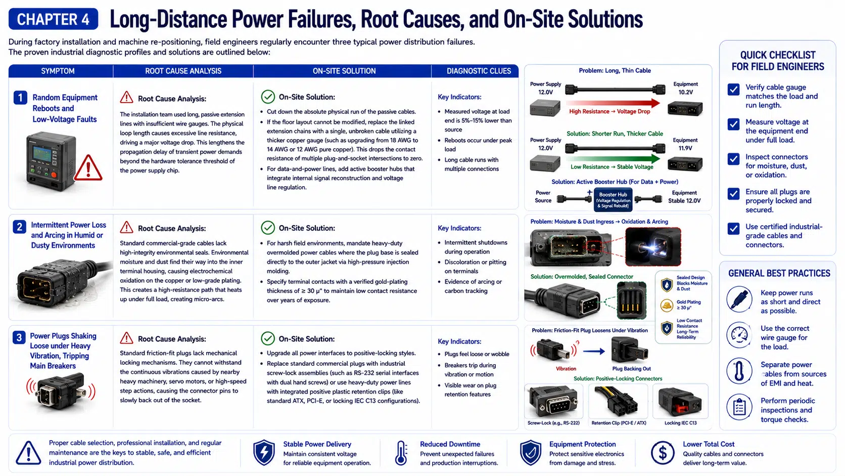
| Observed problem | Possible causes | Checks to perform | Corrective direction |
|---|---|---|---|
| Load resets or undervoltage fault | Excessive cable resistance, weak source, connector loss, peak current | Measure source and load voltage under the real load; inspect the complete path | Correct conductor area, length, contacts, power supply, or distribution architecture |
| Hot connector or terminal | Undersized contact, poor crimp, loose mating, contamination, overload | Inspect terminals and mating surfaces; measure current and temperature under defined conditions | Correct the connection system and root cause; do not only increase wire size |
| Intermittent power during movement | Conductor fatigue, weak strain relief, loose lock, damaged flex zone | Monitor voltage while reproducing motion; inspect bend and termination areas | Redesign flex geometry, cable construction, locking, or strain relief |
| Corrosion or moisture inside connector | Incorrect seal, damaged cavity plug, capillary path, poor routing | Identify the ingress path and verify the complete connector configuration | Replace affected components and correct sealing and routing |
| Fuse or breaker opens | Short circuit, overload, inrush, insulation damage, wrong protection | Follow the equipment diagnostic procedure; isolate sections safely | Repair the fault and coordinate conductor, load, and protective device |
| Noise or communication errors | Coupling from power circuit, grounding issue, poor shield termination | Compare routing and termination with the EMC design; test in the actual equipment | Correct separation, pair geometry, shielding, bonding, or filtering |
| Reference | Typical relevance | What must be specified |
|---|---|---|
| UL 62 | Flexible cords and cables for applicable North American products | Exact cord type, ratings, markings, and product use |
| UL 758 and UL AWM styles | Appliance wiring material used inside equipment | Exact style, temperature, voltage, conductor, insulation, and use restrictions |
| IEC 60320 | Appliance couplers for household and similar equipment | Connector type, rating, temperature condition, mating component |
| IEC 60227 or IEC 60245 series | PVC- or rubber-insulated cable families where applicable | Applicable part, cable designation, voltage, construction, and test requirements |
| IEC 60204-1 | Electrical equipment of machinery | Machine scope, jurisdiction, conductor and installation requirements |
| IPC/WHMA-A-620 | Cable and wire harness workmanship | Revision, class, amendments, and customer acceptance criteria |
These references do not prove WIRES certification or finished-product compliance. A project should identify the exact edition, cable type, component recognition, regional plug requirements, installation code, and evidence required. Product-specific specifications from USB-IF, PCI-SIG, power-supply manufacturers, or equipment OEMs should be used when their interfaces are involved.
Qualification tests demonstrate that a design can meet defined conditions; routine production tests verify each assembly or lot against acceptance criteria. They should not be described as the same activity. The wire harness quality-control guide explains how drawings, process controls, and test evidence fit together.
A structured custom cable development process reduces assumptions before tooling and production. A prototype cable assembly can verify connector fit, pinout, voltage drop, routing, strain relief, and installation before the design is released.
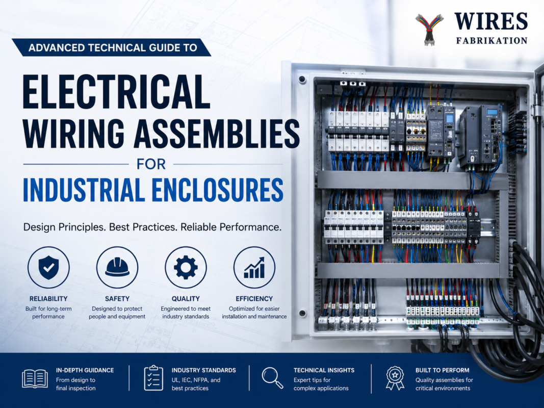
Power cables installed inside control cabinets should also be coordinated with terminal blocks, grounding, wire ducts, heat sources, and service access. See the industrial enclosure wiring guide for cabinet-level routing and assembly decisions.
Use continuous and peak current, total path length, allowable voltage drop, ambient temperature, bundling, duty cycle, insulation class, and protective-device coordination. Then confirm that the terminals and connectors support the selected conductor and load. For a high-current assembly example, see the 6 AWG cable selection guide; the final gauge still depends on the complete project conditions.
No. A larger conductor can reduce resistance but may not fit the terminal, seal, connector, bend space, or strain relief. It can also increase stiffness, weight, and cost. Select the smallest construction that meets all electrical, thermal, mechanical, and regulatory requirements with appropriate margin.
Normally, no. A shield is primarily used for electromagnetic control and is not automatically a current-carrying conductor. Its grounding and termination must follow the system design.
No. Connector shape does not prove conductor size, contact rating, protocol revision, power negotiation, pinout, cable length, or thermal performance. Use the applicable product specification and exact component datasheets.
Common causes include excessive voltage drop, connector resistance, undersized conductors, poor terminations, inadequate strain relief, unsuitable insulation, environmental damage, and an undersized source. Diagnose the complete power path under the real load.
No. The test method and voltage must come from the approved specification. Some assemblies contain electronics or components that can be damaged by an inappropriate test. Continuity and pinout checks are common, while insulation or dielectric tests are project-specific.
Send the electrical load profile, cable length, connector part numbers, environment, drawing, applicable standards, and validation requirements through the WIRES contact page. Clear inputs allow the design to be reviewed without inventing current ratings, test limits, minimum order quantities, or delivery promises.
 English English
 Vietnamese
 Indonesian
 Arabic
 Spanish