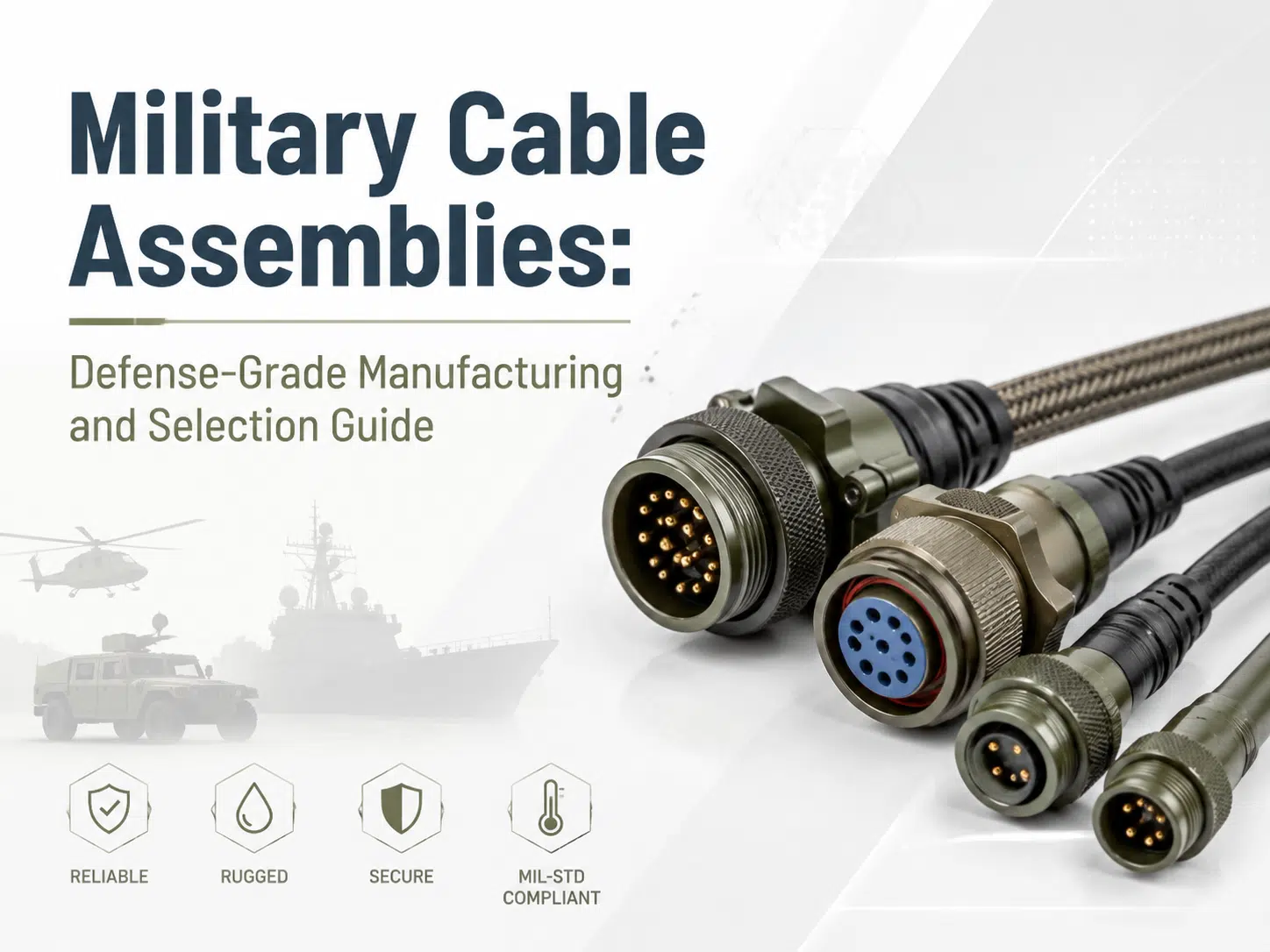
Quick answer: A military cable assembly is a project-specific interconnect built around defined electrical, mechanical, environmental, interface, documentation, and verification requirements. The correct design is not determined by a “military-grade” label alone. It must be traced to the platform specification, applicable standard revisions, approved materials, drawings, and acceptance tests.
This guide explains how engineers and sourcing teams can specify military and aerospace cable assemblies without relying on unsupported performance claims. It also shows which information a manufacturer needs before design review and quotation.
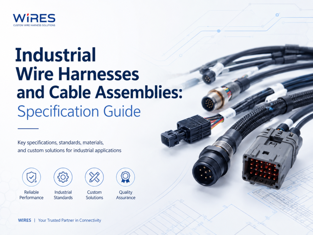
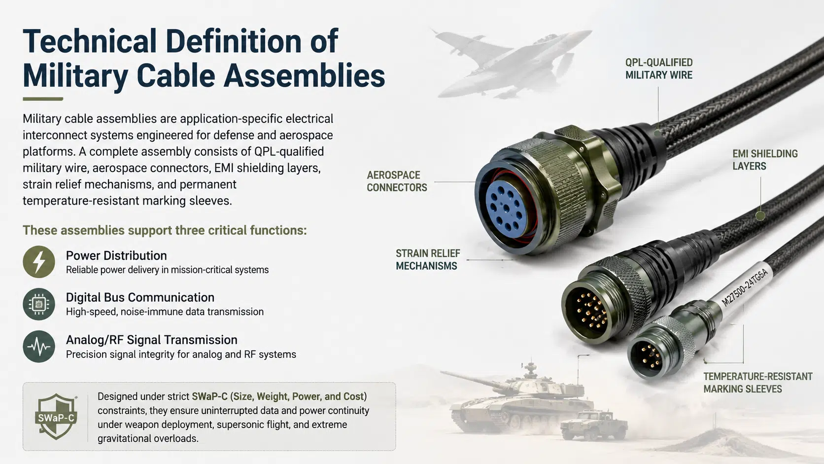
Military cable assemblies route power, control, data, or RF signals between equipment used in defense and aerospace systems. Depending on the application, an assembly may include insulated conductors, twisted pairs, coaxial elements, shielding, connectors, backshells, seals, strain relief, sleeving, labels, and branch protection.
A military assembly differs from a general commercial cable when the project imposes tighter controls on materials, configuration, environmental exposure, traceability, inspection, or qualification. The governing requirements must come from the customer’s drawings, contract, platform specification, and approved standards list. For a broader construction comparison, see the wire harness vs. cable assembly selection guide.
Before selecting a wire, connector, or shield, define what the assembly must do and where it will operate. A useful specification package separates mandatory requirements from preferences.
| Requirement group | Information to define | Why it matters |
|---|---|---|
| Electrical | Voltage, current, signal type, frequency, impedance, allowable voltage drop, grounding approach | Determines conductor size, pair construction, shielding, insulation, and test limits |
| Mechanical | Envelope, routing, branch points, bend limits, flexing, vibration, mating cycles, pull loads | Controls layout, conductor stranding, backshells, clamps, and strain relief |
| Environment | Temperature, altitude, fluids, humidity, salt exposure, dust, water ingress, radiation, fire behavior | Guides insulation, jacket, seal, plating, and protective covering choices |
| Interfaces | Connector part numbers, keying, pin assignments, backshell orientation, mating equipment | Prevents mechanical and electrical incompatibility |
| Compliance | Required standard and revision, customer specifications, approved-source rules, special processes | Defines what must be designed, documented, inspected, and qualified |
| Documentation | Drawings, BOM, certificates, test reports, serialization, change control, packaging | Establishes traceability and acceptance evidence |
Standards should be treated as controlled engineering requirements, not marketing badges. MIL-DTL, MIL-W, MIL-STD, SAE AS, IPC/WHMA-A-620, customer drawings, and platform specifications may cover different parts of the assembly. A standard applies only when the purchase specification or engineering authority calls it out.
Do not assume that every military program requires the same materials or the most severe test profile. Over-specification can increase mass, size, cost, and lead time without improving the actual system.
Select conductor material, plating, strand construction, and cross-sectional area from the electrical load and environmental requirements. Tin-, silver-, and nickel-plated copper serve different temperature, corrosion, termination, and frequency needs. Insulation options such as ETFE, PTFE, FEP, polyimide, cross-linked polymers, and specialty elastomers also involve tradeoffs in wall thickness, flexibility, abrasion resistance, fluid resistance, and processing.
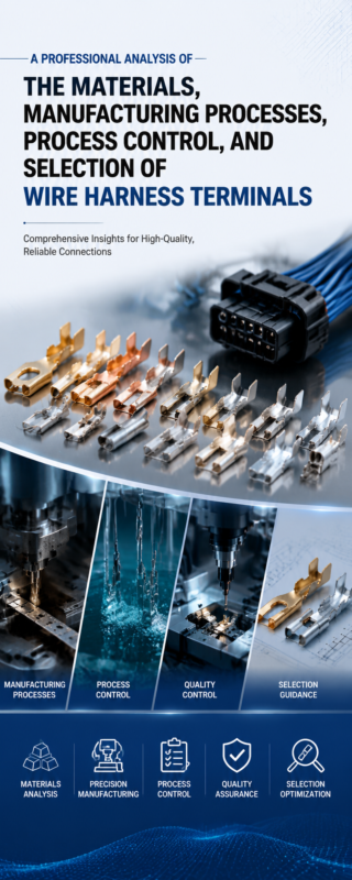
Connector selection must account for circuit density, keying, shell size, contact rating, sealing, shielding termination, mating access, and serviceability. The contact, wire size, crimp tooling, and strip length must form a compatible system. The wire harness terminal and crimping guide explains the basic relationship between terminals, conductor size, plating, tooling, and validation.
Use sleeving, braid, conduit, heat-shrink, boots, potting, grommets, or overmolding only where they address a defined hazard. Where moisture or fluid exposure is expected, sealing details should be coordinated with connector interfaces, cable jacket materials, pressure changes, and inspection access. Review related options in the waterproof cable assembly overview.

Shielding effectiveness depends on the complete current-return path, not braid coverage alone. Cable construction, connector backshells, termination geometry, bonding, enclosure interfaces, routing, and grounding strategy must be designed as one system.
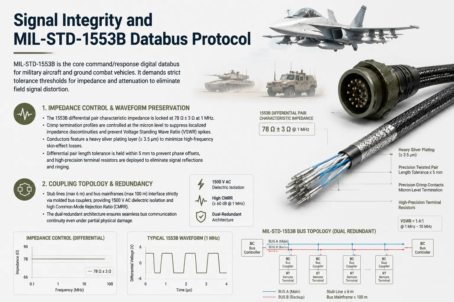
For interfaces such as MIL-STD-1553, use the applicable standard revision and system drawing to define cable impedance, topology, coupling, termination, and verification. Do not copy a generic numeric limit into a drawing without confirming that it matches the platform configuration.
A cable that passes an electrical bench test can still fail in service if the physical installation is poorly controlled. The drawing should define branch locations, connector clocking, minimum bend guidance, support points, service loops, clamp zones, abrasion protection, and areas where the bundle must not be constrained.
Repeatable production begins with a controlled drawing, BOM, tooling plan, work instructions, inspection plan, and change process. A typical custom cable and wire harness process includes requirements review, design-for-manufacturing feedback, material confirmation, prototype build, inspection, electrical testing, and release to production.
Critical operations may include wire preparation, stripping, crimping, soldering, shield termination, splicing, sealing, molding, marking, routing, and final assembly. The required controls depend on the drawing and contract. Examples include approved tooling, setup verification, calibration, operator qualification, first-piece inspection, crimp measurements, pull testing, and documented rework limits.
Qualification demonstrates that a design can meet specified conditions. Production acceptance checks whether each manufactured unit or lot conforms to the released design. These are different activities and should not be presented as interchangeable.
| Verification activity | Typical purpose | When to define it |
|---|---|---|
| Visual and dimensional inspection | Confirm workmanship, labels, branch dimensions, connector orientation, and protection | Normally part of production acceptance |
| Continuity and wiring test | Detect opens, shorts, and pinning errors | Define coverage and test record requirements on the drawing or test plan |
| Insulation resistance or dielectric test | Assess electrical isolation where required | Use customer-approved limits appropriate to the circuit and components |
| Contact resistance or voltage-drop test | Evaluate termination and conductor path performance | Apply when the electrical design requires measurable limits |
| Mechanical pull or retention test | Validate selected termination or process | Define sample size, method, and acceptance criteria |
| Environmental qualification | Evaluate temperature, vibration, shock, fluids, corrosion, ingress, or other exposures | Run to the project-specific profile using appropriate equipment or an approved laboratory |
A supplier’s quality system should connect inspection records to the released configuration. See the wire harness quality control page for an overview of inspection and testing considerations.
| Failure mode | Common contributors | Design or process response |
|---|---|---|
| Intermittent open circuit | Conductor fatigue, poor crimp, unsupported branch, contact damage | Review conductor flexibility, termination process, strain relief, and support spacing |
| Short circuit or insulation damage | Abrasion, sharp edges, excessive heat, fluid incompatibility | Improve routing, edge protection, material selection, and environmental validation |
| Signal degradation | Impedance discontinuity, poor shield termination, excessive untwist, routing near noise sources | Control geometry, backshell design, pair handling, grounding, and installation separation |
| Connector ingress or corrosion | Incorrect seal, damaged interface, incompatible plating, condensation | Specify sealing details, materials, inspection, and environmental tests |
| Configuration mismatch | Outdated drawing, uncontrolled substitution, incorrect keying or pinout | Use revision control, approved substitutions, BOM traceability, and independent verification |
A prototype should answer specific engineering questions before production release. These may include fit, routing, connector access, branch dimensions, electrical performance, shielding termination, serviceability, and test-fixture compatibility. The prototype cable assembly page outlines how early builds can support design verification.
When evaluating a supplier, request evidence relevant to your program rather than relying on broad capability statements:
If the specification is incomplete, identify open assumptions during engineering review instead of hiding them in the quotation.
No. Requirements vary by platform, interface, customer, program, component family, and standard revision. The contract and released engineering documents determine what applies.
No. Component qualification and completed-assembly compliance are separate. The assembly still needs controlled design, manufacturing, inspection, and verification against its own requirements.
Signal type, frequency range, electromagnetic environment, grounding architecture, connector interfaces, routing, flexibility, mass, and required test performance all influence the shielding approach.
Not necessarily. Environmental testing is often part of design qualification or lot validation, while production units receive defined acceptance inspections and electrical tests. The project test plan should state the required frequency.
Physical samples can support dimensional and construction analysis, but a reliable replacement also requires electrical requirements, mating-interface data, environmental conditions, material restrictions, and approval from the design authority.
They should be quoted after reviewing material availability, tooling, documentation, prototype scope, testing, and approval steps. Fixed promises should not be made before the technical package is understood.
Prepare the drawing, interface details, environment, applicable standards, verification plan, quantity range, and documentation requirements before contacting a supplier. Contact WIRES for a military cable assembly requirements review.
 English English
 Vietnamese
 Indonesian
 Arabic
 Spanish