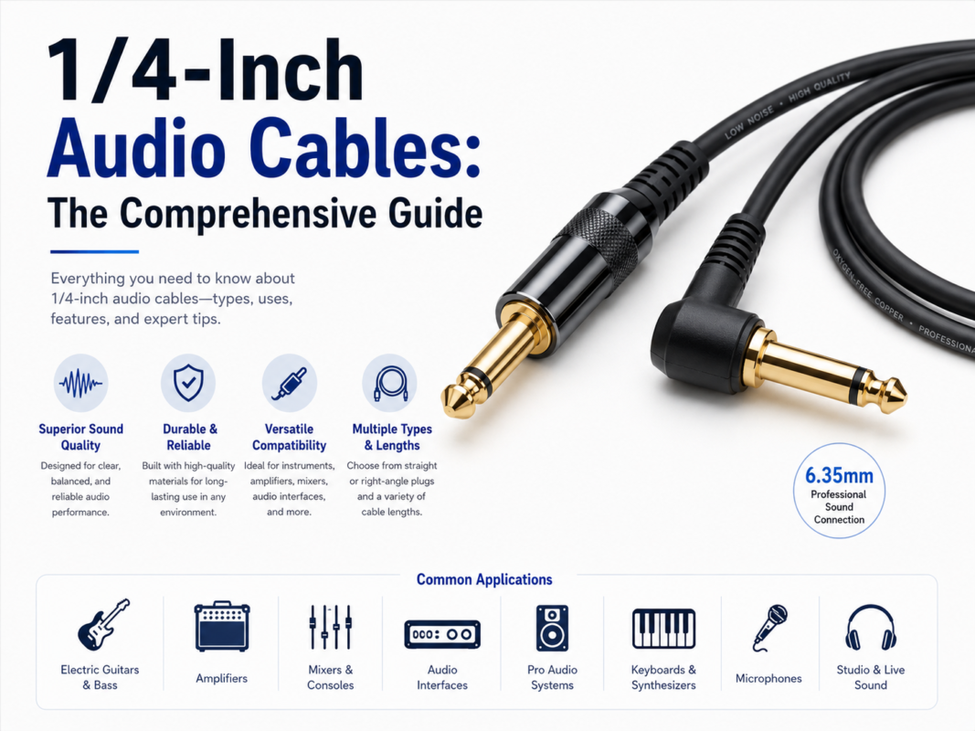
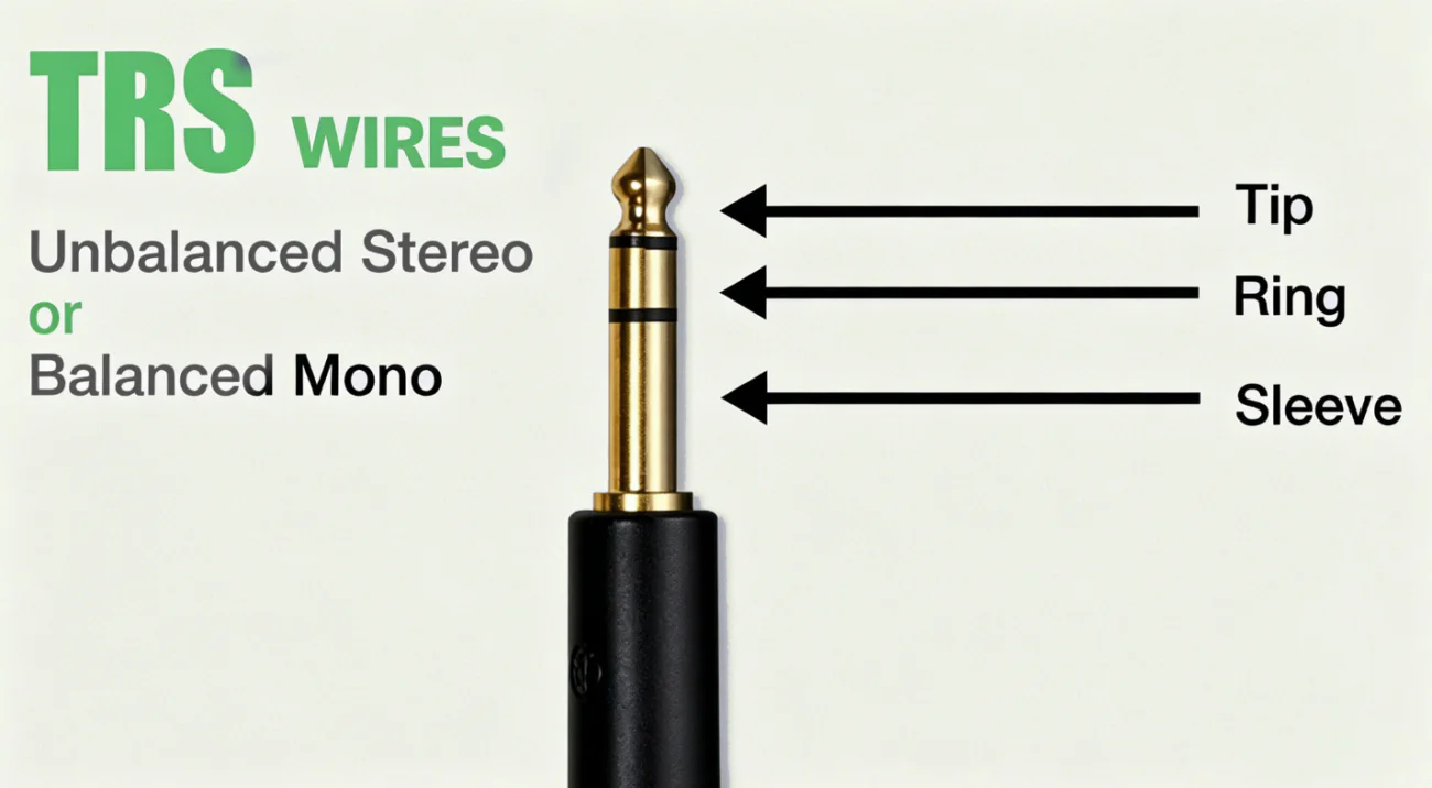
A custom TRS cable assembly is specified by the equipment interface, electrical role, channel mapping, connector orientation, routing, strain relief, labeling, and acceptance criteria—not by the plug shape alone. TRS means Tip-Ring-Sleeve: three conductive contacts. Depending on the equipment, the same connector can carry balanced mono audio, stereo unbalanced audio, mixer insert send/return, control signals, or a TRS-MIDI connection.
This page focuses on professional TRS cable assemblies for equipment integration, patching, breakout, panel connection, labeling, and production control. For choosing a 1/4-inch TS or TRS cable, see the 1/4-inch audio cable guide. For hum diagnosis, follow the dedicated TRS ground-loop noise guide. For basic TRS construction, see TRS cable construction and custom options.
| Use case | Typical TRS contact assignment | Critical verification |
|---|---|---|
| Balanced mono line | Usually Tip = hot, Ring = cold, Sleeve = shield/reference | Both source and input must be balanced and wired for the same convention |
| Stereo unbalanced audio | Usually Tip = left, Ring = right, Sleeve = common return | Confirm headphone, line, or device-specific output behavior |
| Mixer insert | Often Tip = send and Ring = return, but conventions vary | Check the mixer or processor manual before ordering a breakout |
| TRS-MIDI | Tip and Ring mapping can be Type A or Type B | Confirm device pinout and whether an active USB-MIDI interface is involved |
| Control or footswitch | Device-specific switching or expression connection | Do not assume audio cable wiring is compatible with control voltage or resistance sensing |
A TRS connector does not automatically make a channel balanced, stereo, noise-free, or universally compatible. The source circuit, receiving circuit, cable wiring, and complete system determine the result.
| Assembly format | Typical use | Specification details |
|---|---|---|
| Straight patch lead | Rack, mixer, interface, monitor, or instrument connection | Plug size, straight/right-angle exits, length, channel role, jacket and label |
| Y-breakout | Insert cable, stereo breakout, dual-mono routing | Tip/ring map, branch lengths, breakout distance, destination connectors, labels |
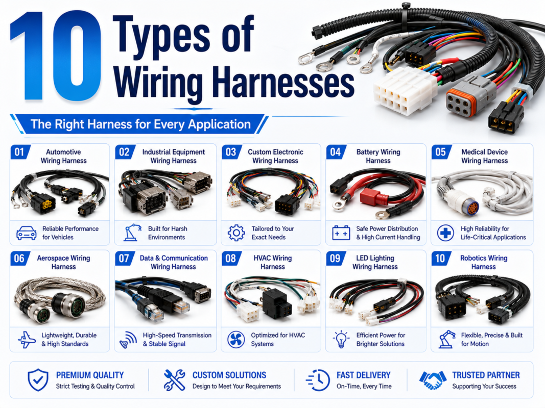
| Multichannel loom | Stagebox, console, rack, test fixture, or equipment bay | Channel count, pair identification, shield architecture, fanout, connector clocking |
| Panel or bulkhead lead | Machine, enclosure, patch panel, or service interface | Panel connector, rear termination, strain relief, sealing boundary, service loop |
| Overmolded lead | Repeated handling or defined cable-exit geometry | Connector geometry, material, bend protection, cable OD, mold interface, artwork |
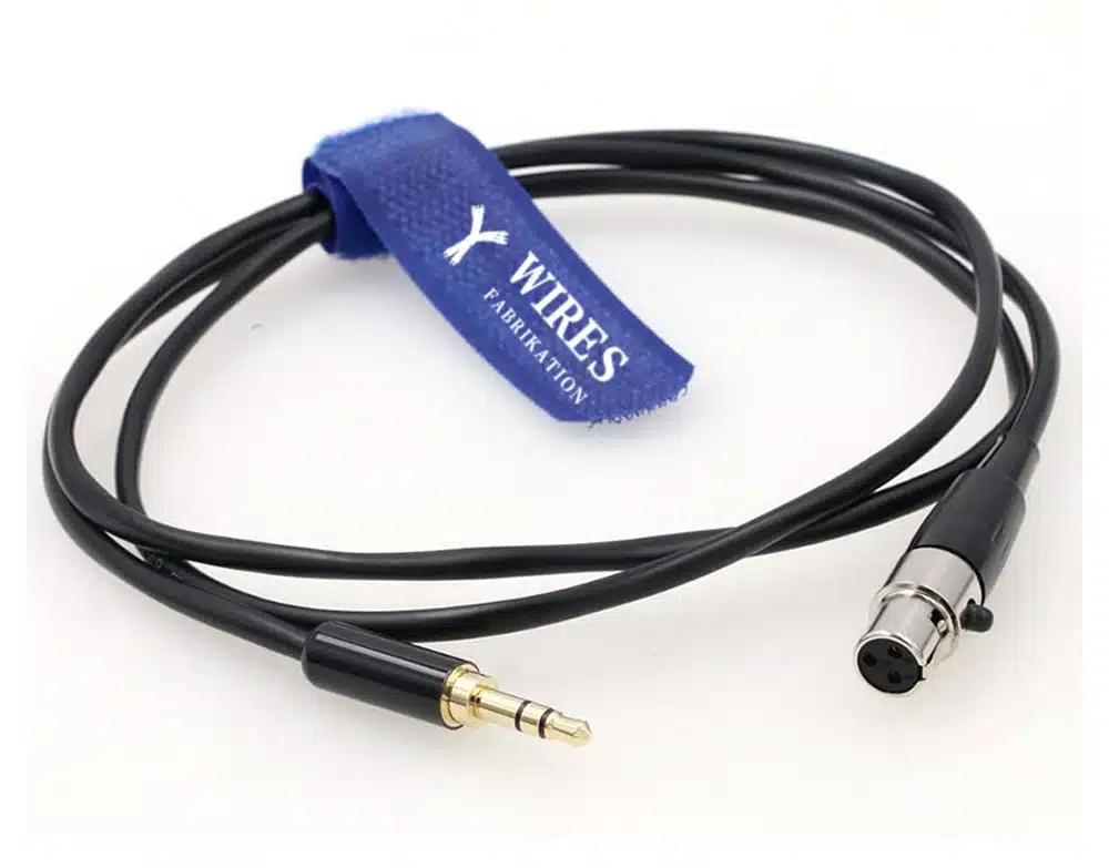
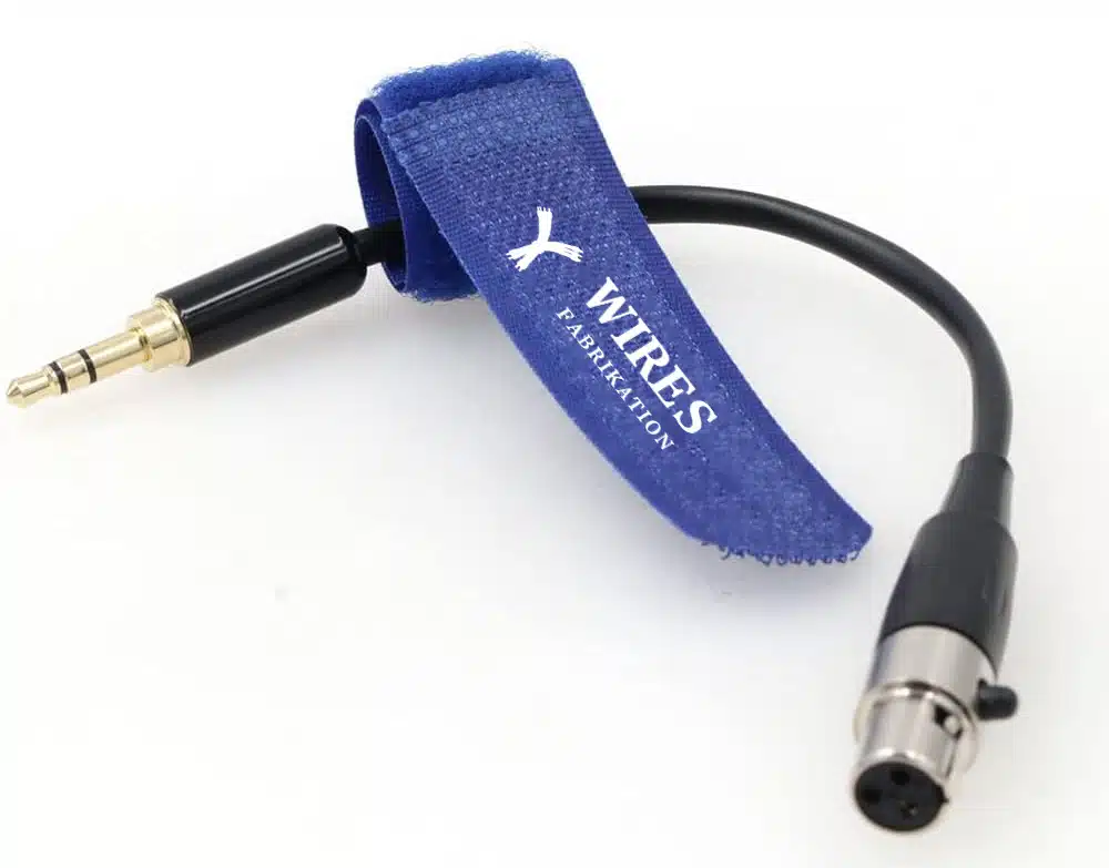
| Adapter assembly | TRS-to-XLR, TRS-to-dual TS, TRS-to-MIDI, or equipment-specific conversion | Electrical direction, pinout, phantom-power risk, active/passive requirement, labels |
For mechanically integrated cable exits, review overmolded cable assemblies. For broader signal and connector choices, see the AV cable selection guide and industrial AV cable assemblies.
In a correctly wired balanced channel, the source provides two signal conductors of opposite polarity and the receiver rejects noise common to both conductors. This can reduce susceptibility to induced interference, but the actual rejection depends heavily on the output circuit, receiver input, impedance balance, grounding, cable geometry, and installation. A cable cannot guarantee a particular common-mode rejection ratio or eliminate every hum, buzz, radio-frequency, or ground-loop problem.
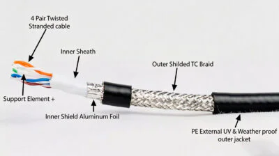
TRS cable construction can use twisted conductors, an overall foil, braid, conductive layers, drain conductors, fillers, and different jackets. The appropriate design depends on the channel, equipment, movement, diameter, bend radius, interference environment, and connector termination. A single material, coverage percentage, or conductor gauge does not prove audio performance.
| Requirement | Questions to define | Evidence |
|---|---|---|
| Static studio or rack use | Route, connector, channel type, service access, noise sources | System wiring diagram and equipment pinout |
| Stage and portable equipment | Handling, coiling, connector retention, abrasion, labels, replacement needs | Handling profile and field acceptance criteria |
| Continuous movement | Travel, bend radius, speed, torsion, support, cycle objective | Motion profile and validation plan |
| Industrial monitoring | Temperature, fluids, vibration, grounding, EMC, enclosure entry | Environment definition and installed-route design |
| Cleaning or laboratory use | Agent, concentration, contact time, wiping, cable and connector exposure | Material compatibility requirement |
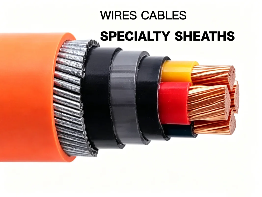
Terms such as “professional,” “low noise,” “high flex,” “oxygen-free copper,” or “industrial grade” should be translated into drawing requirements: conductor construction, pair geometry, shield architecture, jacket compound, finished diameter, bend condition, connector, strain relief, and test method.
The connector-cable junction is a design interface. A robust assembly needs the exact plug family, cable outside diameter, clamp range, solder or crimp method, heat shrink, boot, backshell, exit direction, and strain relief to match the application. A visually neat solder joint does not prove correct electrical or mechanical performance.
| Control | Why it matters |
|---|---|
| Connector part number | Determines contact layout, cable entry, clamp range, plating, and serviceability |
| Pinout drawing | Prevents reversed hot/cold, swapped stereo channels, wrong insert direction, and MIDI Type A/B errors |
| Cable OD and clamp | Controls retention without crushing the jacket or conductors |
| Exit orientation | Avoids panel interference, side load, sharp bends, and incorrect label direction |
| Strain relief | Moves handling load from terminations to the cable support system |
| Shield termination | Affects noise, chassis bonding, and potential ground-current paths |
| Inspection and test | Confirms pinout, continuity, shorts, workmanship, labeling, and required function |
IPC/WHMA-A-620 may be used as a project workmanship reference only when the applicable revision, class, product scope, customer requirement, and acceptance criteria are specified. Referencing it does not state that WIRES or every TRS cable assembly is certified to a particular class.
Custom TRS assemblies often fail through documentation rather than material selection: the left and right branch may be swapped, a send/return breakout may be reversed, a right-angle plug may point the wrong way, or identical black cables may be impossible to service. Build identification into the assembly.
For TRS-based MIDI integrations, review the custom MIDI cable specification guide and the general MIDI cable guide.
| Stage | What to check | Record |
|---|---|---|
| Design review | Interface, electrical role, pinout, cable construction, labels, route, environment | Approved drawing, BOM, and requirements list |
| First article | Connector orientation, lengths, breakout, cable OD, labels, workmanship | First-article inspection and sample approval |
| Electrical acceptance | Continuity, shorts, pin mapping, shield path, and required functional check | Tester program, fixture revision, results, and limits |
| System validation | Actual source/destination, mode, route, startup, noise behavior, and interference environment | Configuration, conditions, observations, and pass criteria |
| Mechanical validation | Handling, bend, retention, vibration, flexing, or fluid exposure when required | Method, samples, condition, duration, and acceptance criteria |
Do not promise a universal cable length, noise floor, insertion loss, bend life, shielding effectiveness, or test coverage. Use the actual interface, route, environment, and acceptance requirement to choose the validation method.
WIRES’ process and services and customized process explain the development route for equipment cable assemblies. Review available certification information separately; a standard reference does not make an unverified TRS assembly compliant with an application.
No. TRS describes three contacts, not one universal signal format. It can carry balanced mono, stereo unbalanced, insert send/return, MIDI, or device-specific control wiring.
No. A correctly implemented balanced channel can improve rejection of common noise, but equipment design, grounding, routing, cable construction, and the receiving input determine the result. Never defeat protective earth to solve hum.
Both can use the same plug, but an insert cable usually maps Tip and Ring to different send and return branches, while stereo TRS typically maps them to left and right. Follow the exact equipment manual.
There is no universal rule. Consider the source impedance, receiver impedance, cable capacitance, route, frequency content, noise environment, connector transitions, and required system performance; validate the actual channel.
No. The pinout, phantom-power boundary, source and destination type, direction, and balanced/unbalanced implementation matter. A passive adapter can be inappropriate or unsafe for a particular interface.
Provide channel count, equipment models, pinout, connector and orientation, branch order, lengths, shielding strategy, labels, route, environment, and acceptance tests.
Typical checks include drawing review, connector and label verification, continuity, shorts, pin mapping, shield path, workmanship, and any customer-required functional or mechanical tests. The exact coverage must be defined in the control plan.
A dependable custom TRS assembly begins with the full channel definition: electrical role, equipment interface, connector map, route, environment, documentation, and validation. Send drawings, equipment details, pinouts, labels, and test requirements through the WIRES contact page for an assembly review.
 English English
 Vietnamese
 Indonesian
 Arabic
 Spanish