Car Stereo Wiring Colors: A Comprehensive Guide
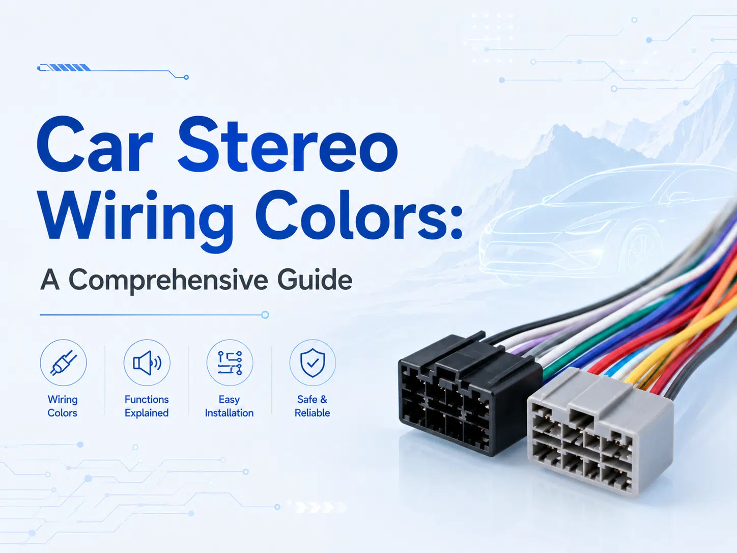
Are you installing a new car stereo? Do you know what accessories you need? First, you need to understand the car stereo wiring colors and codes. Second, ensure the wiring harness adapter matches your vehicle specifications.
The good news is that the CEA (Consumer Electronics Association) has listed all color coding standards. You just need to connect the correct harness to the correct terminals. This article will further introduce the colors in the audio wiring harness. Please read on!
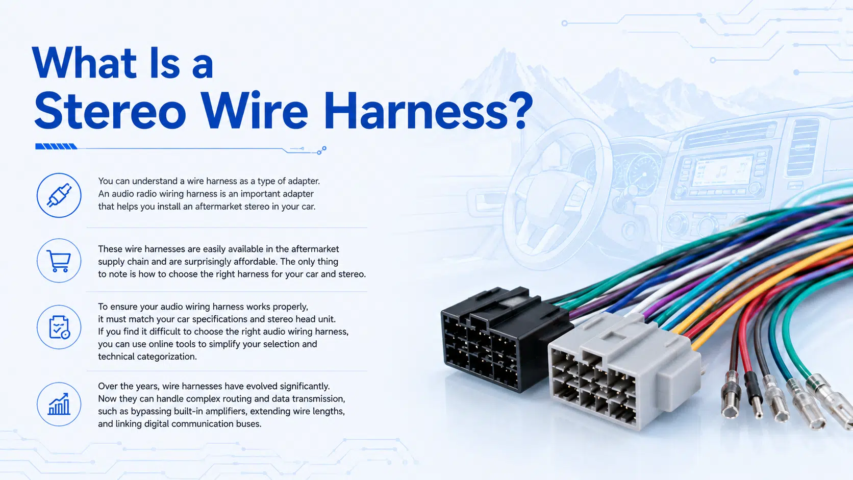
What Is a Stereo Wire Harness?
You can understand a wire harness as a type of adapter. An audio radio wiring harness is an important adapter that helps you install an aftermarket stereo in your car.
These wire harnesses are easily available in the aftermarket supply chain and are surprisingly affordable. The only thing to note is how to choose the right harness for your car and stereo.
To ensure your audio wiring harness works properly, it must match your car specifications and stereo head unit. If you find it difficult to choose the right audio wiring harness, you can use online tools to simplify your selection and technical categorization.
Over the years, wire harnesses have evolved significantly. Now they can handle complex routing and data transmission, such as bypassing built-in amplifiers, extending wire lengths, and linking digital communication buses.
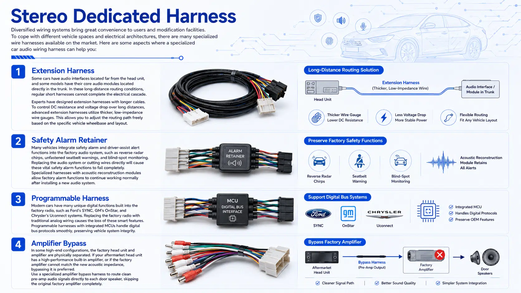
Stereo Dedicated Harness
Diversified wiring systems bring great convenience to users and modification facilities. To cope with different vehicle spaces and electrical architectures, there are many specialized wire harnesses available on the market. Here are some aspects where a specialized car audio wiring harness can help you:
Extension Harness
Some cars have audio interfaces located far from the head unit, and some models have their core audio modules located directly in the trunk. In these long-distance routing conditions, regular short harnesses cannot complete the electrical cascade.
Experts have designed extension harnesses with longer cables. To control DC resistance and voltage drop over long distances, advanced extension harnesses utilize thicker, low-impedance wire gauges. This allows you to adjust the routing path freely based on the specific vehicle wheelbase and layout.
Safety Alarm Retainer
Many vehicles integrate safety alarm and driver-assist alert functions into the factory audio system. These include reverse radar chirps, unfastened seatbelt warnings, and blind-spot monitoring alerts.
Therefore, after replacing the audio system or cutting wires directly, these vital safety alarm functions will fail completely. This can create hazardous driving conditions.
Fortunately, there are specialized harnesses on the market equipped with acoustic reconstruction modules. These allow the factory alarm functions to continue working normally after installing a new audio system.
Programmable Harness
Today’s modern cars have many unique digital functions built into the factory radio, making the wiring connections and signal interactions more complex. Examples include Ford’s SYNC system, GM’s OnStar system, and Chrysler’s Uconnect system.
Replacing the factory radio with traditional analog wiring causes the loss of these built-in smart functions. However, technology changes daily, and you can still enjoy these convenient features after replacing the radio.
There are better programmable harnesses on the market equipped with integrated microcontrollers (MCUs) that handle digital bus protocols smoothly. These premium harness assemblies require extra investment, but they are worth the money to preserve vehicle system integrity.
Amplifier Bypass
In some high-end configurations, the factory audio head unit and the amplifier (power amplifier) are physically separated. During an upgrade, you can choose to cascade the factory amplifier with the modified aftermarket system.
However, if your aftermarket head unit already features a high-performance built-in amplifier chip, or if the factory amplifier cannot match the new acoustic impedance, bypassing it is preferred.
You can use a specialized amplifier bypass harness to route the clean pre-amp audio signal directly to each door speaker, skipping the original factory amplifier hardware completely.
 How to Find the Right Wire Harness?
 How to Find the Right Wire Harness?
Finding the right wiring harness adapter is simple. You only need some basic vehicle information to verify compatibility in the supply chain. This mainly depends on your target vehicle’s initial electrical configuration. Please check the following five aspects:
Exact year of production
Vehicle make and brand
Specific model code
Whether your vehicle is equipped with a factory amplifier system (as this dictates the need for an impedance-attenuating balanced harness)
Whether your vehicle currently has an aftermarket radio installed
If your vehicle already has an aftermarket radio installed, you generally do not need to buy a new harness. The previous installer already deployed an adapter harness during the initial installation.
On the other hand, if you are connecting to a factory amplifier system, you must select a specialized adapter harness to provide an impedance-matched low-level signal to the factory amplifier.
Original factory wire harnesses vary greatly between manufacturers and do not follow aftermarket standards:
Ford: Harnesses often change pins during mid-cycle refreshes. The factory constant wire may be light green with a purple stripe, while the main ground wire may be black with a light green stripe.
Toyota: Typically uses two specific plastic housings. The factory constant is usually a thick blue wire with a yellow stripe, while the ignition wire appears as a grey wire. A specialized Toyota stereo wiring harness translates these cleanly into standard aftermarket colors.
Honda: Internal wire cross-sections are designed tightly. The factory constant memory wire is often pure white or red-striped, while the ignition power is pure yellow or red-striped. Without an adapter harness, it is easy to confuse the factory pure yellow wire (ignition) with the aftermarket standard yellow wire (constant), causing head unit memory loss.
Chevrolet: Generally utilizes digital local area network bus technology (such as OnStar). You typically won’t find a traditional 12V ignition power wire in the factory plug, as the factory unit is awakened by digital bus signals. Replacing the radio requires a programmable custom automotive wiring harness with an integrated data decoding chip to allow proper power cycling.
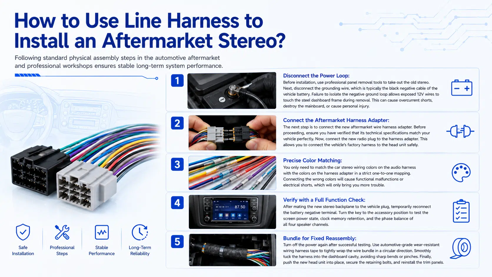
How to Use Line Harness to Install an Aftermarket Stereo?
Following standard physical assembly steps in the automotive aftermarket and professional workshops ensures stable long-term system performance:
Disconnect the Power Loop: Before installation, use professional panel removal tools to take out the old stereo. Next, disconnect the grounding wire, which is typically the black negative cable of the vehicle battery. Failure to isolate the negative ground loop allows exposed 12V wires to touch the steel dashboard frame during removal. This can cause overcurrent shorts, destroy the mainboard, or cause personal injury.
Connect the Aftermarket Harness Adapter: The next step is to connect the new aftermarket wire harness adapter. Before proceeding, ensure you have verified that its technical specifications match your vehicle perfectly. Now, connect the new radio plug to the harness adapter. This allows you to connect the vehicle’s factory harness to the head unit safely.
Precise Color Matching: You only need to match the car stereo wiring colors on the audio harness with the colors on the harness adapter in a strict one-to-one mapping. Connecting the wrong colors will cause functional malfunctions or electrical shorts, which will only bring you more trouble.
Verify with a Full Function Check: After mating the new stereo backplane to the vehicle plug, temporarily reconnect the battery negative terminal. Turn the key to the accessory position to test the screen power state, clock memory retention, and the phase balance of all four speaker channels.
Bundle for Fixed Reassembly: Turn off the power again after successful testing. Use automotive-grade wear-resistant wiring harness tape to tightly wrap the wire bundle in a circular direction. Smoothly tuck the harness into the dashboard cavity, avoiding sharp bends or pinches. Finally, push the new head unit into place, secure the retaining bolts, and reinstall the trim panels.
Which Color Wires Should Be Connected Together in a Car Stereo?
 Which Color Wires Should Be Connected Together in a Car Stereo?
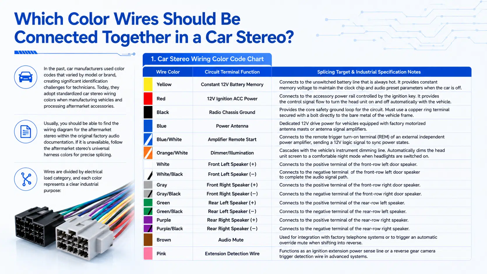
In the past, car manufacturers used color codes that varied by model or brand, creating significant identification challenges for technicians. Today, they adopt standardized car stereo wiring colors when manufacturing vehicles and processing aftermarket accessories.
Usually, you should be able to find the wiring diagram for the aftermarket stereo within the original factory audio documentation. If it is unavailable, follow the aftermarket stereo’s universal harness colors for precise splicing.
Wires are divided by electrical load category, and each color represents a clear industrial purpose:
1. Car Stereo Wiring Color Code Chart
| Wire Color | Circuit Terminal Function | Splicing Target & Industrial Specification Notes |
| Yellow | Constant 12V Battery Memory | Connects to the unswitched battery line that is always hot. It provides constant memory voltage to maintain the clock chip and audio preset parameters when the car is off. |
| Red | 12V Ignition ACC Power | Connects to the accessory power rail controlled by the ignition key. It provides the control signal flow to turn the head unit on and off automatically with the vehicle. |
| Black | Radio Chassis Ground | Provides the core safety ground loop for the circuit. Must use a copper ring terminal secured with a bolt directly to the bare metal of the vehicle frame. |
| Blue | Power Antenna | Dedicated 12V drive power for vehicles equipped with factory motorized antenna masts or antenna signal amplifiers. |
| Blue/White | Amplifier Remote Start | Connects to the remote trigger turn-on terminal (REM) of an external independent power amplifier, sending a 12V logic signal to sync power states. |
| Orange/White | Dimmer/Illumination | Cascades with the vehicle’s instrument dimming line. Automatically dims the head unit screen to a comfortable night mode when headlights are switched on. |
| White | Front Left Speaker (+) | Connects to the positive terminal of the front-row left door speaker. |
| White/Black | Front Left Speaker (-) | Connects to the negative terminal of the front-row left door speaker to complete the audio signal path. |
| Gray | Front Right Speaker (+) | Connects to the positive terminal of the front-row right door speaker. |
| Gray/Black | Front Right Speaker (-) | Connects to the negative terminal of the front-row right door speaker. |
| Green | Rear Left Speaker (+) | Connects to the positive terminal of the rear-row left speaker. |
| Green/Black | Rear Left Speaker (-) | Connects to the negative terminal of the rear-row left speaker. |
| Purple | Rear Right Speaker (+) | Connects to the positive terminal of the rear-row right speaker. |
| Purple/Black | Rear Right Speaker (-) | Connects to the negative terminal of the rear-row right speaker. |
| Brown | Audio Mute | Used for integration with factory telephone systems or to trigger an automatic override mute when shifting into reverse. |
| Pink | Extension Detection Wire | Functions as an ignition extension power sense line or a reverse gear camera trigger detection wire in advanced systems. |
Need Batch Customization of High-Reliability Automotive Wire Harnesses?
 Need Batch Customization of High-Reliability Automotive Wire Harnesses?
As a professional contract manufacturer with 28 years of industry experience in industrial and automotive cable assemblies, WIRES delivers tier-one solutions tailored to your technical drawings and electrical schematics:
OEM Replacement Harnesses: Replicating original factory connector footprints and electrical characteristics precisely.
Custom Radio Wiring Harnesses: Configuring low-loss jumper assemblies with customized lengths tailored to your aftermarket product requirements.
Amplifier Bypass & Bus Integration Harnesses: Integrating digital decoding chips to preserve steering wheel controls and factory safety alarms.
IATF 16949 Certified Manufacturing: Utilizing automated crimp force monitoring (CFM) to ensure a reliable electrical connection even under vibration and temperature cycling.
For volume procurement, prototype sampling, or contract manufacturing inquiries, contact our engineering office to receive factory-direct quotations.
2. Car Stereo Wire Color Cheat Sheet
This reference card helps clarify core wiring logic quickly on-site or on the factory floor:
Core Power Circuit Trio:
Yellow = 12V Constant Power (Memory Retention)
Red = 12V Ignition ACC (Switched Power Control)
Black = Chassis Safety Ground
Front Speaker Symmetrical Pairs:
White = Front Left (+) | White/Black = Front Left (-)
Gray = Front Right (+) | Gray/Black = Front Right (-)
Rear Speaker Symmetrical Pairs:
Green = Rear Left (+) | Green/Black = Rear Left (-)
Purple = Rear Right (+) | Purple/Black = Rear Right (-)
3. Aftermarket Radio Wiring Diagram Reference
Technical personnel frequently utilize image searches for spatial layout reference. We recommend configuring a clear, original stereo wiring diagram vector illustration at this position within your CMS system:
Technical Content Placement Note: Insert a high-resolution wiring layout schematic mapped to the table above.
Image SEO Optimization: Set the alternative text property to “Standard aftermarket car stereo wiring harness color code diagram and pinout definition.”
Frequently Asked Questions
Q1: Why is my car stereo not turning on after installation?
This is typically caused by an open circuit on the main power lines. Use a digital multimeter to check the main harness: verify that the yellow wire shows a stable 12V battery voltage when the car is completely off; verify that the red wire switches to 12V when the key is turned to the ACC position. If both lines show proper voltage, the black ground wire is likely connected to a painted car panel, creating high contact resistance that blocks the return loop.
Q2: Can I connect the red and yellow wires together to a constant power source?
This configuration is discouraged under standard technical guidelines. Shorting the yellow wire (constant memory) and red wire (ignition ACC) directly to the battery bypasses the vehicle’s power management system. The head unit’s decoding chips and display modules will remain in a high-draw standby state 24 hours a day. This creates a continuous parasitic drain of 50 mA to 150 mA, which can flatten a standard 45Ah car battery completely in 4 to 5 days.
Q3: Why do my car speakers sound weak and completely lack bass?
This indicates speaker phase cancellation caused by an accidental positive/negative reversal on a channel. For example, if you connect the green/black wire (negative) and pure green wire (positive) backward on the rear left channel, that speaker will move outward while the others move inward, creating a 180-degree acoustic phase variance. This causes sound waves to cancel out in the low-frequency range (20 Hz to 120 Hz), resulting in a hollow acoustic field that cannot be corrected by software equalizers.
Q4: What wire specifications and standards are required for car audio wiring harnesses?
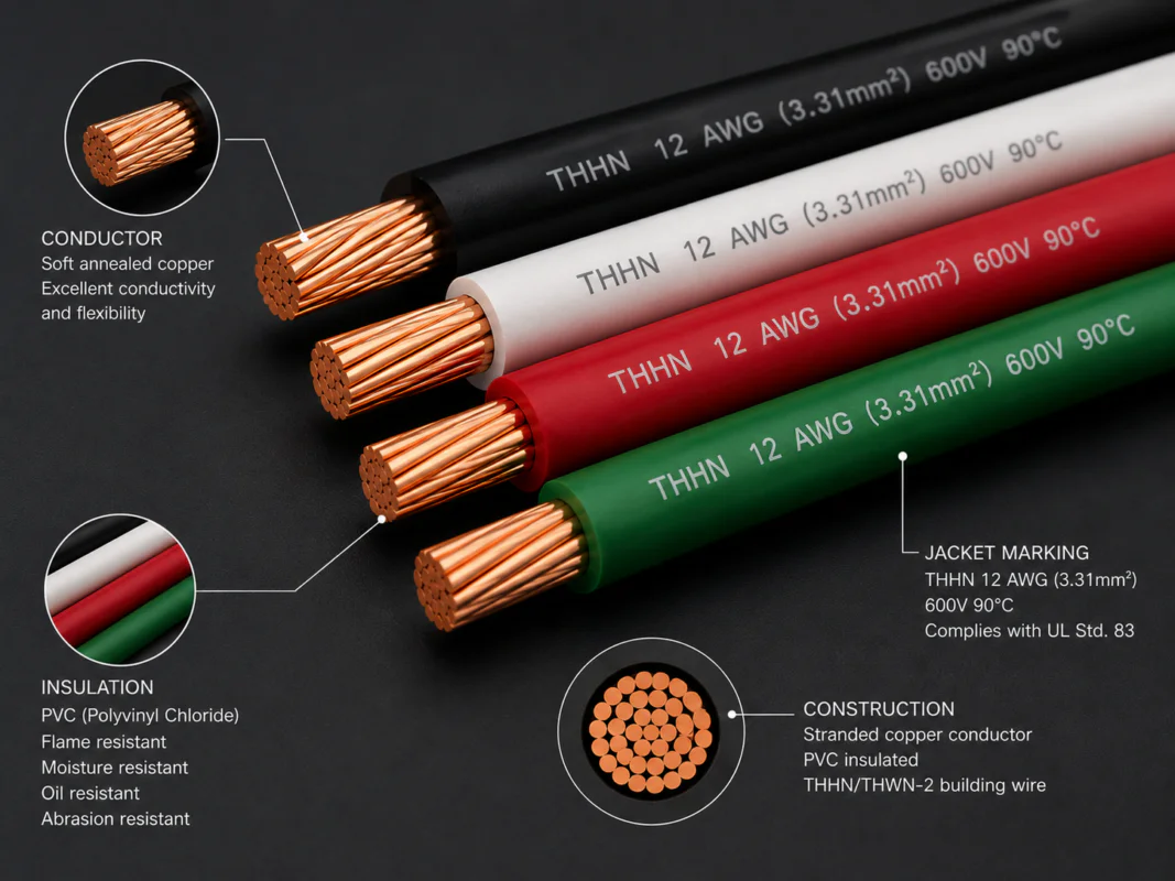
Standard automotive power distribution rules require that the yellow constant and red ignition wires use heavy 16 AWG or 14 AWG copper conductors to handle continuous current loads of 10A to 15A without thermal buildup. Multi-channel speaker lines utilize 18 AWG or 20 AWG wire sizes to balance cross-sectional layout space with electrical impedance. High-quality builds feature cross-linked polyolefin (XLPE) insulation compliant with SAE J1128 or ISO 6722 to withstand cabin temperatures up to 125°C and pass a 15-second vertical flame test.
Q5: How does WIRES guarantee long-term mechanical reliability under vehicle vibration?
Vehicles expose wiring assemblies to continuous alternating mechanical shock from 10 Hz to 500 Hz. Following IPC-WHMA-A-620 Class 3 criteria, WIRES integrates automated pull-testers on the assembly line, validating that the axial retention force of 16 AWG crimped terminals exceeds the 133 Newton (N) threshold. Crimp height (CH) and crimp width (CW) tolerances are monitored within a strict ±0.03mm window to maintain an airtight, gas-tight mechanical joint. We accommodate small-batch orders down to 100 sets with an average production lead time of 7 to 14 business days.
Conclusion
The adoption of standardized car stereo wiring colors resolves historical installation challenges stemming from conflicting manufacturer codes. Whether managing cross-border fleet procurement or sourcing volume aftermarket components, enforcing uniform color standards and strict crimp quality controls on the production floor is fundamental to achieving a long service life for cabin electronics.
When your commercial programs require high-shielding, low-attenuation wiring solutions that meet strict physical pull-test and environmental resilience baselines, partnering with an experienced automotive wiring harness manufacturer is vital.
WIRES combines 28 years of engineering expertise with a robust framework to support your volume production demands. Contact our technical team to review your engineering prints and secure factory-direct pricing.