6 AWG building wire is commonly considered for feeders, larger branch circuits, HVAC equipment, workshops, outbuildings, and selected grounding or bonding applications. Whether it is permitted—and how much current it may carry—depends on conductor material, insulation marking, wiring method, terminal temperature rating, ambient temperature, conductor count, overcurrent protection, equipment instructions, and the electrical code adopted by the local authority.
This guide explains United States building-wire selection. It is not a substitute for a project calculation, permit review, or installation by a qualified electrician. For batteries, vehicles, marine equipment, and custom low-voltage leads, use the separate 6 AWG custom cable guide; building-wire ampacity tables do not automatically apply to cable assemblies.
American Wire Gauge defines nominal conductor geometry. A 6 AWG solid round conductor has a nominal area of about 13.3 mm² and a nominal diameter of about 4.11 mm. These values identify the gauge; they do not state the finished wire diameter, insulation thickness, voltage rating, allowable current, or suitability for a location.
Stranded building wire uses multiple strands to achieve the required conductor area. The finished outside diameter and pulling behavior depend on the insulation system, conductor class, strand construction, and manufacturer. Always match lugs, breakers, splices, connectors, glands, and pulling equipment to the exact listed product and conductor material.
| Gauge information | What it establishes | What it does not establish |
|---|---|---|
| 6 AWG | Nominal conductor size in the AWG system | Final ampacity or breaker size |
| Approximately 13.3 mm² | Nominal equivalent conductor area | Interchangeability with a metric cable size |
| Approximately 4.11 mm | Nominal diameter for solid round wire | Diameter of stranded or insulated wire |
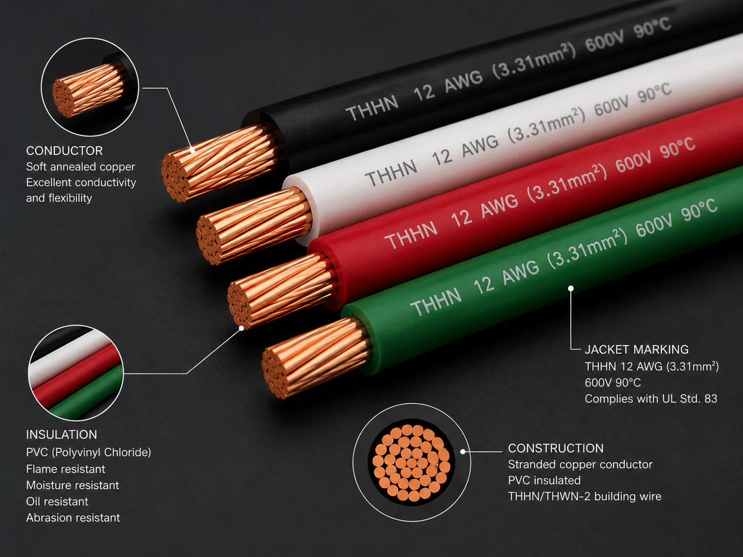
The marking printed on the product is more important than its color or appearance. Verify the complete legend, listing, conductor material, size, voltage rating, temperature rating, and location rating before specification.
| Type | Typical construction and location | Important limits |
|---|---|---|
| THHN/THWN-2 | Individual thermoplastic-insulated conductors, commonly installed in raceway; many products carry both markings | Use only the ratings printed on the exact product. Raceway fill, wet-location rules, temperature correction, conductor count, and terminal ratings still apply. |
| XHHW-2 | Individual cross-linked-polyethylene-insulated conductors for raceway or other approved wiring methods | Confirm wet/dry marking, conductor material, pulling requirements, and the adopted code. |
| NM-B | Nonmetallic-sheathed cable for permitted dry-location residential work | Not a wet-location cable. NEC rules generally require NM-B ampacity to use the 60°C conductor column even when its conductors have higher insulation ratings. |
| SER | Service-entrance cable, Type SER, often used for feeders where the code and product listing permit | SER means service-entrance cable, not “server ingress.” Installation, support, wet-location, and ampacity rules depend on the application. |
| USE-2 | Underground service-entrance conductor intended for specified underground and wet-location uses | USE-2 alone is not a general indoor branch-circuit marking. Interior use requires an additional suitable marking and an approved wiring method. |
| RHH/RHW-2 | Thermoset-insulated conductors marked for the listed dry or wet conditions | Confirm raceway, location, flame, sunlight, and installation requirements from the complete marking. |
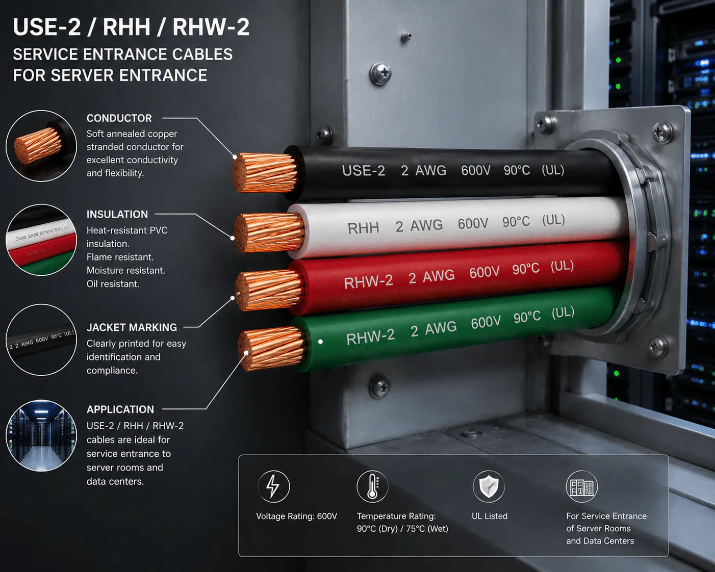
Terms such as “600 V,” “90°C,” “sunlight resistant,” “wet location,” or “direct burial” are product markings with specific scopes. One marking does not imply the others. A 90°C insulation marking also does not mean equipment terminals can operate at 90°C or that the conductor may always use the 90°C ampacity column.
The following values are a reference from NFPA 70 (NEC) 2023, Table 310.16 for not more than three current-carrying conductors in raceway, cable, or earth, based on a 30°C ambient condition. They are not universal final ampacities.
| 6 AWG conductor | 60°C column | 75°C column | 90°C column |
|---|---|---|---|
| Copper | 55 A | 65 A | 75 A |
| Aluminum or copper-clad aluminum | 40 A | 50 A | 55 A |
Source and scope: NFPA 70, 2023 edition, Table 310.16. Confirm the edition adopted in the project jurisdiction and the exact table applicable to the wiring method. Local amendments and equipment instructions can change the design result.
The 90°C column is often used as a starting point for adjustment or correction when the conductor is rated 90°C, but the final allowable ampacity cannot exceed the applicable terminal and equipment limitations. A licensed designer or electrician should document the calculation for the actual installation.
| Application | Why 6 AWG may be considered | Information required before selection |
|---|---|---|
| Feeder to a subpanel | Load, distance, and wiring method may point to a larger conductor | Calculated load, conductor material, number of conductors, neutral treatment, raceway or cable type, terminals, and local code |
| HVAC or heat-pump equipment | Equipment nameplate and installation instructions may require this size | Minimum circuit ampacity, maximum overcurrent protection, conductor temperature rating, disconnect, and terminal data |
| Workshop or fixed equipment | Motors, welders, compressors, or other loads may need a dedicated circuit | Equipment duty, motor or welder rules, inrush, nameplate, receptacle or disconnect, and conductor route |
| Outbuilding supply | Load and distance can make voltage drop important | Feeder calculation, grounding and bonding arrangement, burial or raceway method, wet-location marking, and local inspection requirements |
| EV supply equipment | Some EVSE circuits may use 6 AWG, depending on the equipment and installation | Continuous-load calculation, equipment rating, terminal temperature, wiring method, conductor material, and manufacturer instructions |
| Grounding or bonding | Some code calculations result in 6 AWG | Purpose of conductor, electrode or bonding path, service or feeder data, physical protection, and the adopted NEC article |
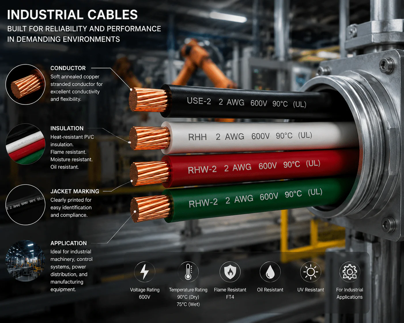
Do not choose a building conductor from a general application list. HVAC, motor, EVSE, service, feeder, grounding, and renewable-energy circuits have different calculation and installation rules. The equipment label and approved instructions are part of the specification.
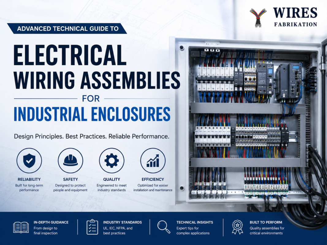
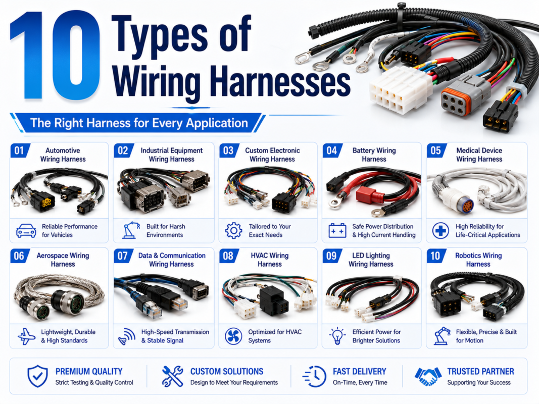
Inside machines and control cabinets, wiring may fall under equipment standards rather than general premises-wiring assumptions. For those projects, review industrial enclosure wiring, industrial wire harnesses, and high-voltage cable options.
Copper and aluminum are not interchangeable merely because both are marked 6 AWG. The NEC reference table assigns different ampacities, and the termination must be identified for the conductor material. The equipment lug, connector, antioxidant preparation when required, installation instructions, torque method, and inspection plan must all match the chosen conductor.
| Factor | Copper | Aluminum or copper-clad aluminum |
|---|---|---|
| Reference ampacity | Higher than the same AWG aluminum entry in NEC Table 310.16 | Use the aluminum or copper-clad-aluminum column |
| Termination | Use terminals marked for copper and the specified strand construction | Use terminals specifically identified for the conductor material and follow surface-preparation instructions |
| Size and routing | May allow a smaller AWG than aluminum for the same design target | A larger conductor may be needed; verify raceway fill and bending space |
| Installation control | Correct strip length, seating, and torque remain essential | Material compatibility, preparation, seating, and torque are especially important |
Overheating at a connection can result from loose hardware, incorrect torque, damaged strands, incompatible lugs, oxidation, excessive load, poor enclosure conditions, or repeated thermal cycling. The conductor material alone does not prove the root cause.
A conductor may satisfy ampacity rules and still produce excessive voltage drop. Calculate the complete circuit path using the actual one-way distance, conductor resistance at operating temperature, load current, phase and circuit arrangement, and connection resistance.
DC or single-path approximation: Vdrop = I × Rloop
For AC systems, use the appropriate single-phase or three-phase method and include power factor and reactance when they are material to the result. Online calculators are useful only when their assumptions match the actual conductor, temperature, circuit, and installation.
NEC informational notes commonly reference approximately 3% voltage drop for a branch circuit and 5% total for feeder plus branch circuit as design guidance for reasonable operation. These notes are not a universal permission to ignore equipment voltage limits, and the adopted edition or project specification may impose different requirements.
| Input | Evidence | Common error |
|---|---|---|
| Load current | Load calculation or equipment data | Using breaker rating as the normal operating current |
| Route length | Plan, field measurement, and routing allowance | Using one-way length when the formula requires a complete loop |
| Conductor data | Manufacturer resistance data and material | Using a generic copper value for aluminum or a different temperature |
| Allowable equipment voltage | Nameplate and manufacturer instructions | Assuming a generic percentage is acceptable for every load |
For a deeper explanation of conductor resistance and complete-loop loss, see the custom power cable design guide.
| Risk | Possible consequence | Prevention |
|---|---|---|
| Wrong ampacity column | Overheated conductor or unnecessary oversizing | Use the adopted table and the lowest applicable equipment or installation limit |
| Dry-location cable in a wet raceway | Insulation deterioration or failed inspection | Specify conductors marked for the actual location |
| Incorrect aluminum termination | High connection resistance and heat | Use identified terminals, preparation, tooling, and torque instructions |
| Excessive conduit fill or tight bends | Damaged insulation and difficult pulling | Calculate fill, bending space, and pulling conditions before installation |
| Long circuit without voltage-drop review | Low equipment voltage, nuisance operation, or poor starting | Calculate the complete path and compare with equipment limits |
| Assuming a 90°C wire permits 90°C ampacity | Overloaded terminals or equipment | Apply conductor derating, then respect the final terminal and equipment limit |
| Unverified breaker or equipment combination | Noncompliant protection or damaged equipment | Coordinate nameplate, conductor, overcurrent device, and instructions |
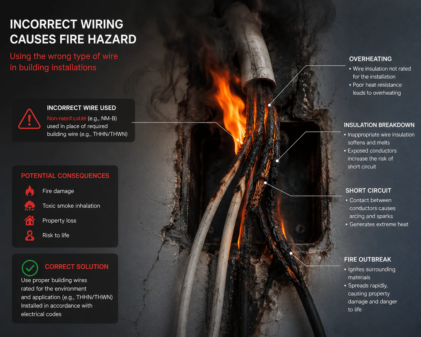
A photograph of heat damage cannot establish why a failure occurred. Root-cause work should preserve the conductor, terminal, breaker, enclosure, and load evidence; record torque and installation details; and distinguish overload, loose connection, incompatible material, insulation damage, moisture, and external heat.
WIRES’ process and services and customized manufacturing process describe support for equipment cable and harness projects. Review available certification information separately; a standards reference in this article does not state that every WIRES product is listed or certified for building installation.
Under the specific conditions of NEC 2023 Table 310.16, 6 AWG copper appears as 55 A in the 60°C column, 65 A in the 75°C column, and 75 A in the 90°C column. The final allowable ampacity may be lower after applying terminal, cable, ambient-temperature, conductor-count, load, and equipment rules.
Sometimes, but gauge alone cannot answer the question. The conductor material, temperature column, wiring method, load calculation, terminal rating, equipment instructions, correction and adjustment factors, and special circuit rules must all support the selected overcurrent device.
No. They have different ampacity entries and termination requirements. Use the correct conductor-material column, compatible lugs, manufacturer instructions, and a complete circuit calculation.
THHN alone is not a wet-location designation. Many products are dual-marked THHN/THWN-2, but the exact conductor legend and approved raceway or wiring method must be verified. Outdoor raceways are generally treated as wet locations.
NM-B is intended for permitted dry locations and is not made suitable for a wet location merely by placing it in conduit. Use a wiring method and conductors listed for the actual environment and local code.
USE-2 by itself is not a general interior building-wire designation. A conductor may also carry RHH, RHW-2, or another marking that permits an approved interior use. Check the complete marking and adopted code before specifying it.
No. Voltage drop depends on current, conductor material, route length, temperature, circuit configuration, and connection resistance. Calculate the actual circuit and compare it with equipment limits and project guidance.
Reliable building-wire selection starts with the load, location, equipment, adopted code, and wiring method—not a standalone ampacity number. For an equipment-side cable or harness review, send the drawing, electrical requirements, mating components, environment, and validation needs through the WIRES contact page. Building installation and code approval should remain with the responsible licensed professional and local authority.
 English English
 Vietnamese
 Indonesian
 Arabic
 Spanish