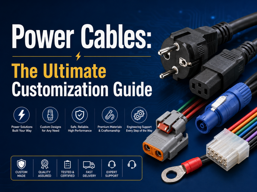
A 6 AWG cable is a heavy-gauge conductor commonly considered for battery feeds, inverters, charging systems, industrial DC power, marine equipment, and other high-current connections. The gauge alone does not determine safe current. A reliable assembly must also match the conductor material, strand construction, insulation system, circuit length, termination, ambient temperature, bundling, duty cycle, and governing equipment standard.
This guide focuses on custom 6 AWG cable assemblies and low-voltage equipment wiring. For building branch circuits and premises-wiring rules, use the locally adopted electrical code and the separate building-application guidance rather than treating a cable-assembly recommendation as a code calculation.
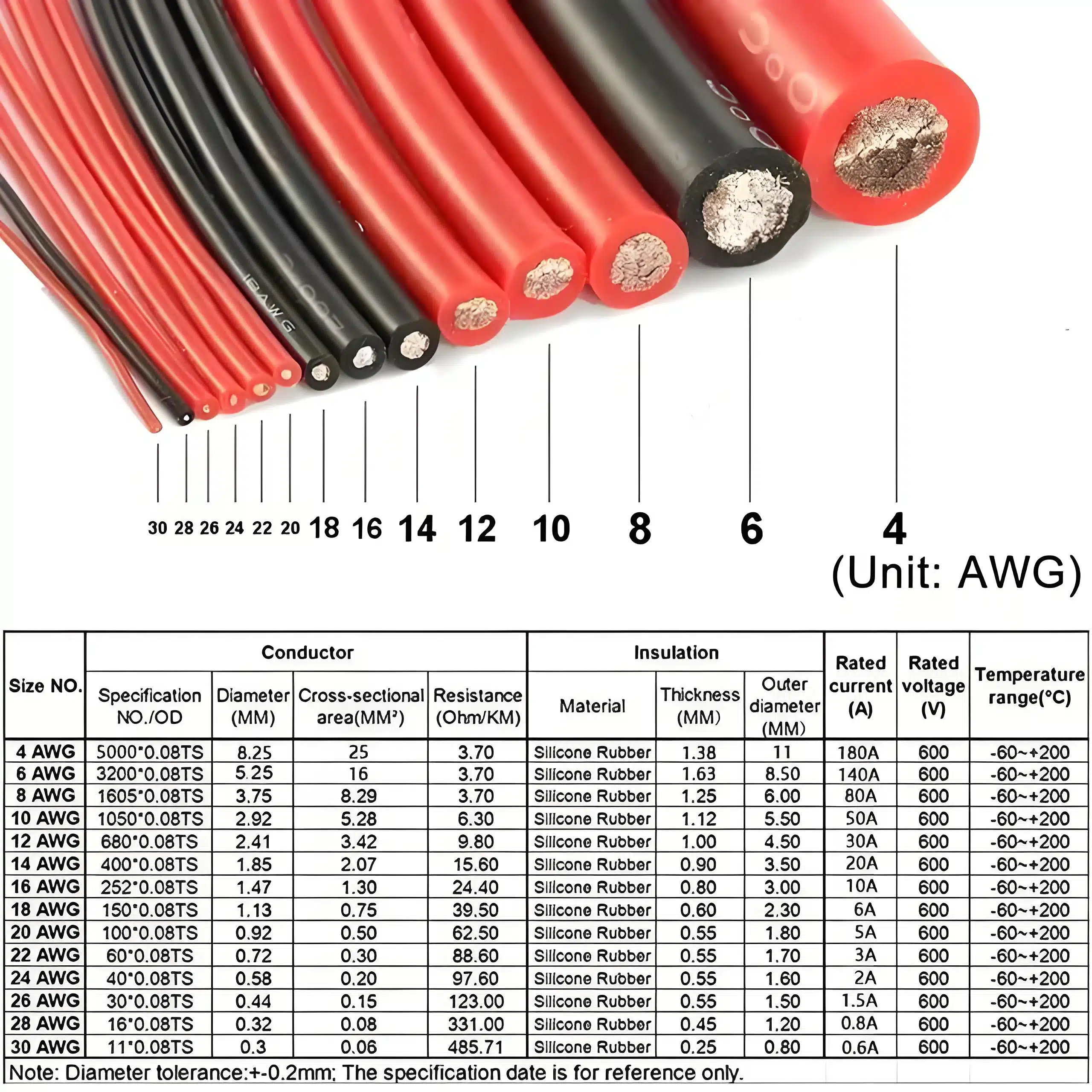
AWG is the American Wire Gauge system. As the AWG number decreases, the nominal conductor area increases. A 6 AWG solid round conductor has a nominal area of about 13.3 mm² and a nominal diameter of about 4.11 mm. These are gauge geometry references, not finished-cable dimensions or current ratings.
Stranded 6 AWG cable uses multiple wires to achieve the required conductor area. Strand count and strand diameter affect flexibility, termination behavior, outer diameter, and fatigue resistance, but they do not remove the need to verify conductor resistance and finished-cable construction against the applicable drawing or supplier data.
| Property | What 6 AWG tells you | What still requires verification |
|---|---|---|
| Conductor size | Nominal AWG area | Material, plating, stranding, and resistance |
| Flexibility | Not defined by gauge alone | Strand design, lay length, insulation, and bend conditions |
| Ampacity | Not a single universal value | Standard, temperature, bundling, installation, and terminal limits |
| Voltage drop | Lower than a smaller conductor under comparable conditions | Complete circuit length, current, temperature, and connection resistance |
| Finished diameter | Not defined by bare-conductor area | Insulation wall, jacket, shielding, and manufacturing tolerance |
For a broader explanation of conductors, terminals, connectors, and protection, see what a wire harness is. If the project may be better treated as a cable rather than a routed harness, compare wire harnesses and cable assemblies.
Six-gauge cable is selected when an electrical calculation and the equipment requirements point to this conductor size. Typical projects include short high-current DC connections, battery and inverter leads, charging equipment, motor or actuator power, generator and auxiliary circuits, and power distribution inside industrial equipment.
| Application | Key design questions | Common customization |
|---|---|---|
| Battery and inverter leads | Continuous and peak current, polarity, fault protection, routing, and terminal temperature | Ring terminals, boots, labels, paired leads, and abrasion protection |
| Marine and mobile equipment | Moisture, salt, fluids, vibration, service access, and overcurrent protection | Tinned conductor when specified, sealed transitions, adhesive heat shrink, and corrosion-resistant hardware |
| Solar and energy-storage equipment | System voltage, fault current, connector system, temperature, polarity, and product standard | Color coding, touch protection, matched positive/negative sets, and documented crimp tooling |
| Industrial machinery | Duty cycle, cabinet temperature, movement, routing, chemical exposure, and maintenance | Flexible stranding, conduit or braid, bulkhead transitions, and identification |
| Vehicle and agricultural equipment | Vibration, heat zones, fluids, clamps, service loops, and connector retention | Vehicle-specific terminals, branch protection, convoluted tube, braid, and sealed connectors |
Related design examples are covered in the guides to custom power cables, automotive electrical harnesses, and agricultural machinery wire harnesses.
There is no responsible universal ampacity for every 6 AWG cable. A value taken from one table may apply only to a particular conductor material, insulation temperature rating, number of current-carrying conductors, ambient condition, installation method, or equipment category. The connector, terminal, fuse, PCB, busbar, or enclosure may become the limiting component before the conductor does.
Use the rule set that applies to the product and installation. Examples may include the adopted electrical code for premises wiring, SAE or ISO cable specifications for vehicles, ABYC requirements for marine installations, or an OEM drawing for industrial equipment. The exact edition and project scope matter. A standard reference does not by itself state that WIRES or a finished assembly is certified to that standard.
A higher-temperature insulation rating does not automatically authorize more current. The conductor, termination, adjacent materials, enclosure, and governing rule must all support the design.
Low-voltage systems often reach their voltage-drop limit before they reach a conductor temperature limit. Calculate resistance over the complete current path, including both supply and return conductors, terminals, splices, connectors, and temperature effects.
Voltage drop: Vdrop = I × Rloop
Power loss: Ploss = I² × Rloop
Use conductor resistance from the specified cable data sheet or an approved measurement, not a generic online calculator alone. Copper resistance increases with temperature, and contact resistance can become significant at high current. For intermittent loads, assess the real duty cycle and the equipment’s minimum operating voltage rather than averaging away a short but important drop.
| Input | Why it matters | Evidence to request |
|---|---|---|
| One-way cable length | The electrical loop may be twice the visible run | Harness drawing and routing allowance |
| Operating current | Determines conductor and contact voltage drop | Load profile, inrush record, or equipment specification |
| Conductor resistance | Varies with material, size, construction, and temperature | Cable data sheet or measured resistance |
| Connection resistance | Crimps, bolted joints, and connectors add loss and heat | Terminal data, process record, and validation result |
| Allowable drop | Depends on source voltage and equipment tolerance | System requirement or OEM specification |
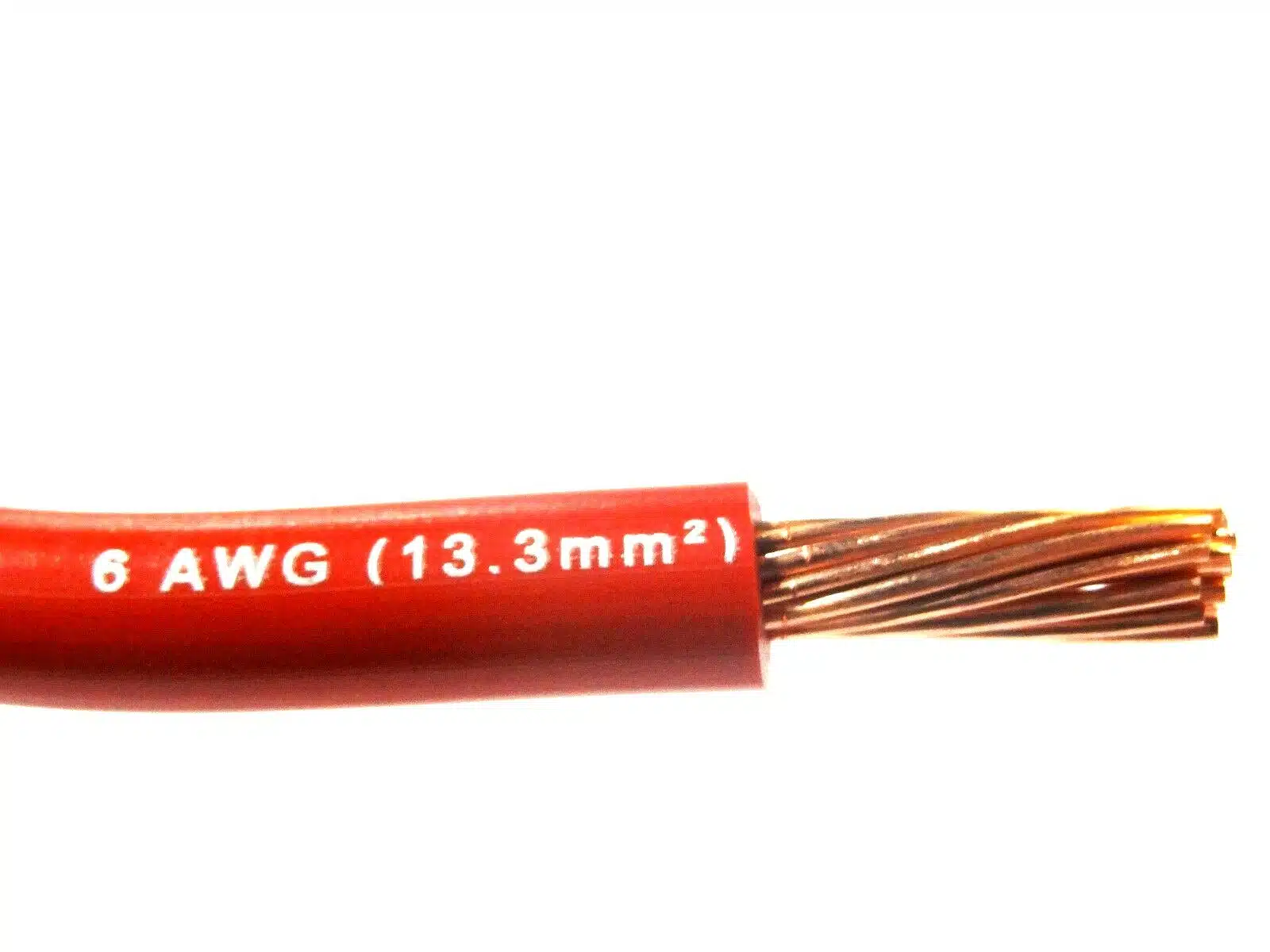
Bare copper is common where the environment and termination system permit it. Tinned copper may be specified for corrosion resistance or compatibility with a particular cable standard, but tinning is not a substitute for sealing, drainage, strain relief, or correct terminal plating. If aluminum or another conductor material is proposed, the connector system and assembly process must be designed and approved for that material.
More and finer strands can improve handling and bend performance, but “high-flex” is not a complete specification. Repeated-motion projects should define bend radius, travel, speed, acceleration, torsion, cycle objective, temperature, support method, and acceptance criteria. A cable suitable for occasional installation bends may not be suitable for continuous drag-chain or robotic motion. See the robotic cable assembly page for motion-specific design considerations.
| Requirement | Questions for the specification |
|---|---|
| Temperature | What are the normal, peak, cold-start, and nearby-component temperatures? |
| Fluids and chemicals | Which oils, fuels, cleaners, coolants, or process chemicals contact the cable? |
| Moisture and ingress | Is exposure splash, condensation, immersion, pressure washing, or salt atmosphere? |
| Flame and smoke | Which exact product, vehicle, marine, rail, or building requirement applies? |
| Abrasion | Where can the cable rub, clamp, or pass through an edge or bulkhead? |
| Motion | Is the cable static, service-flexed, continuously flexed, or twisted? |
Do not select PVC, XLPE, silicone, TPE, or another material by name alone. Review the exact compound data, wall thickness, finished dimensions, approvals, and compatibility with overmolding, seals, heat shrink, and the operating environment.
A 6 AWG conductor needs a terminal designed for the exact conductor construction and insulation diameter. A terminal labeled only by a broad wire-size range may still be incompatible with the strand bundle, barrel geometry, plating, stud size, connector housing, or crimp tooling.
For high-current cable assemblies, define:
Visual appearance alone cannot prove a sound high-current crimp. Cross-section analysis, dimensional checks, pull testing, resistance measurement, and load-temperature validation may be required according to the drawing and quality plan. For failure mechanisms at interfaces, review the guides to terminal retention and terminal corrosion and heat damage.
| Design element | Available project choices | Information needed |
|---|---|---|
| Length and routing | Straight lead, paired leads, branches, service loops | Dimensioned drawing and tolerance |
| Ends | Ring, lug, tab, splice, connector, or bare preparation | Exact mating part and orientation |
| Protection | Heat shrink, boots, braid, conduit, sleeve, grommets | Environment, edge, abrasion, and service requirements |
| Identification | Color, printed markers, labels, polarity, serial data | Label content, location, durability, and traceability |
| Sealing | Adhesive heat shrink, connector seals, overmolded transitions | Ingress condition and test method |
| Assembly grouping | Positive/negative pair, kit, harness branch, installed hardware | BOM, packaging, installation sequence, and torque ownership |
Customization should reduce installation risk, not merely change appearance. A good drawing controls polarity, terminal clocking, breakout position, label orientation, protection overlap, exposed conductor, critical dimensions, and inspection points.
Before production, build representative samples with the intended cable, terminals, tooling, protection, and mating hardware. The validation plan should reflect the actual risks rather than applying every possible test.
| Check | Purpose | Typical evidence |
|---|---|---|
| Dimensions and orientation | Confirm fit, routing, and installation | First-article report against the drawing |
| Continuity and polarity | Detect open, shorted, or reversed circuits | Test record and fixture revision |
| Crimp process | Confirm conductor and terminal compatibility | Crimp dimensions, pull data, and cross-section when required |
| Voltage drop or resistance | Verify the complete high-current path | Method, current, temperature, lead compensation, and limit |
| Load-temperature test | Identify hot conductors or interfaces | Current profile, ambient, stabilization rule, and measurement locations |
| Environmental test | Evaluate moisture, fluids, vibration, heat, or flexing | Project standard, sequence, samples, and acceptance criteria |
WIRES can review a drawing, BOM, mating components, and test requirements as part of its cable assembly process and services. The customized process is the right place to confirm prototype and installation details before the production drawing is released. Production acceptance should follow the approved inspection and change-control plan; review available certification information separately when a project requires documented evidence.
For premises wiring rather than an equipment cable assembly, selection must follow the locally adopted installation code, conductor material, termination, and installation conditions. See the 6 AWG building wire guide for that separate application path.
No. 6 AWG has a nominal area of about 13.3 mm², so it is not interchangeable with a 6 mm² metric conductor. Terminals, seals, cable glands, and electrical calculations must match the actual conductor and finished cable.
No. Ampacity depends on the governing rule, conductor material, insulation, temperature, bundling, installation, duty cycle, and termination limits. Use the table or standard that applies to the actual equipment and verify the assembled circuit.
Use the operating current multiplied by the resistance of the complete supply-and-return path. Include cable length, conductor temperature, terminals, connectors, splices, and other interfaces. Compare the result with the equipment’s allowable input-voltage range.
Not automatically. Fine stranding can improve flexibility, but the finished cable must still meet its specified resistance, temperature, installation, and product requirements. The compatible terminal and crimp process are equally important.
Use the conductor construction required by the vessel design and applicable marine standard. Tinned copper may be appropriate, but corrosion control also depends on sealing, drainage, terminal plating, routing, strain relief, and maintenance.
Only when the exact cable construction is designed and validated for the defined motion. Specify bend radius, travel, speed, acceleration, torsion, support, temperature, and cycle acceptance criteria; gauge alone does not indicate flex life.
Provide the drawing or route dimensions, electrical load profile, cable specification, terminal and mating part numbers, environment, protection details, test requirements, quantity, and packaging needs. If the design is incomplete, start with the interface and risk information rather than guessing part numbers.
A dependable 6 AWG cable assembly comes from matching the conductor, insulation, terminals, routing, protection, and validation plan to the real application. Send WIRES your drawings, mating components, load information, and environmental requirements through the engineering contact form for a manufacturability review.
 English English
 Vietnamese
 Indonesian
 Arabic
 Spanish