5G and Medical Coaxial Cables: Types and Selection Guide
Coaxial cables for 5G and medical equipment must be selected from the complete signal path, not from a generic cable name. The required frequency band, impedance, attenuation, phase or delay, connector interface, routing, thermal condition, electromagnetic environment, cleaning exposure, and verification method depend on the exact equipment and intended use.
5G radio modules, antenna feeders, laboratory instruments, imaging systems, sensors, displays, and internal medical modules may all use coaxial interconnects, but their design limits are different. This guide provides a practical framework for engineers and buyers to compare cable types without treating one construction, connector, rating, or material as universal.
5G and Medical Coaxial Cable Selection at a Glance
| Decision | Questions to answer | Evidence to request |
|---|---|---|
| Frequency | What is the operating band, bandwidth, harmonic content, and test band? | Equipment specification and exact cable and connector data |
| Impedance | Does the source, cable, connector, adapter, and load use the same nominal impedance? | Interface drawings, part numbers, and return-loss requirements |
| Loss budget | What cable length, transitions, temperature, and receiver margin apply? | Complete-channel attenuation or insertion-loss data |
| Phase and timing | Are channels length matched or phase controlled? | Frequency, reference plane, temperature, and matching method |
| EMC and shielding | What external fields, leakage limits, bonding, and routing conditions exist? | Shield construction, termination, installation, and test plan |
| Mechanical use | Is the cable fixed, flexed, twisted, portable, or installed in a compact module? | Bend, torsion, vibration, strain, and service requirements |
| Medical environment | Is there cleaning, disinfection, patient contact, sample contact, MRI, or high-voltage exposure? | Intended use, risk file, material evidence, and complete-device requirements |
| Validation | Which electrical, mechanical, environmental, and functional tests are required? | Defined methods, fixtures, calibration, limits, samples, and reports |
For general coaxial construction and common impedance families, see the coaxial cable guide. For industrial loss, power, motion, and environmental selection, review the industrial and RF coaxial cable selection guide.
How Coaxial Cables Carry 5G and Medical Signals
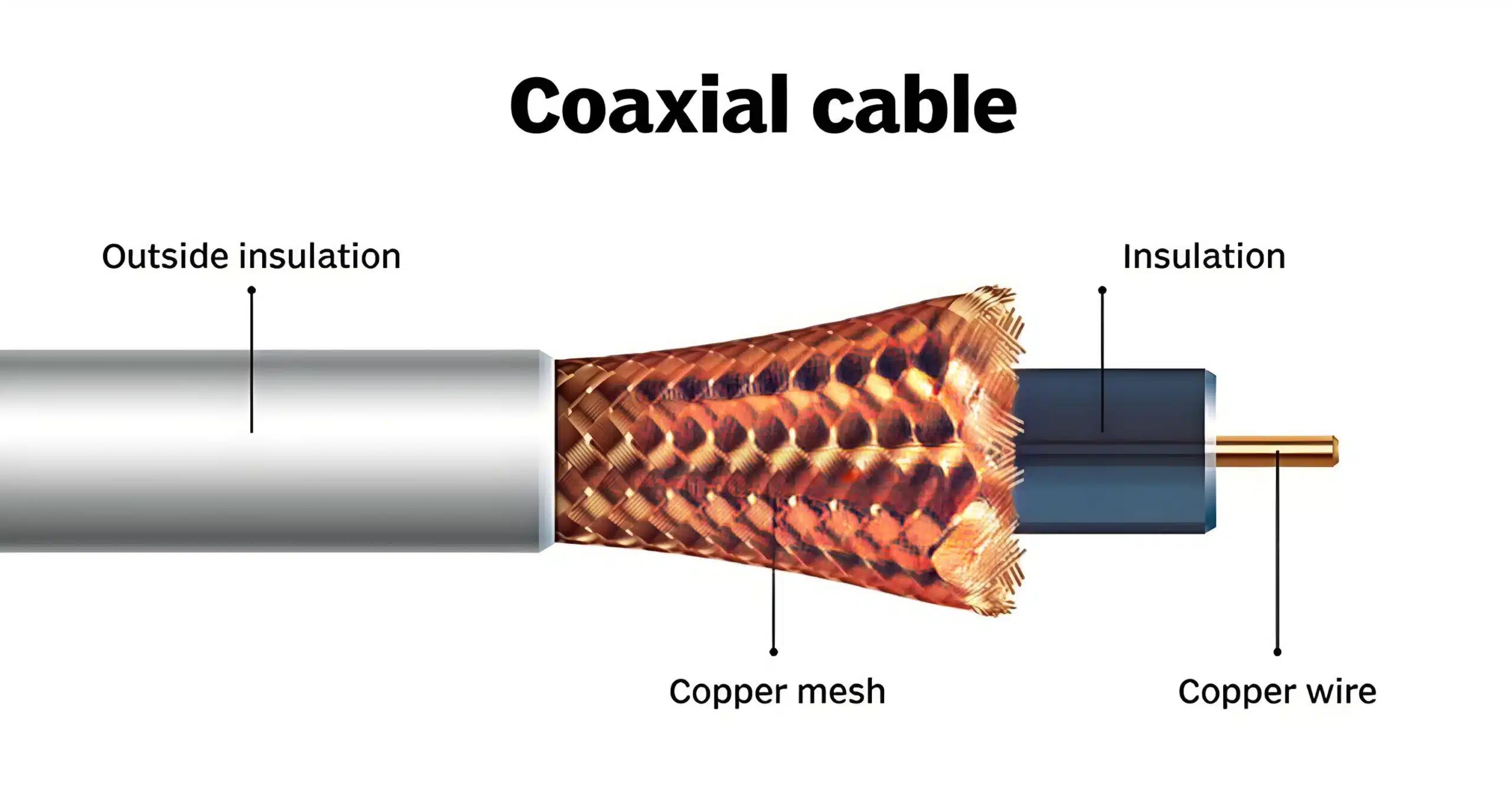
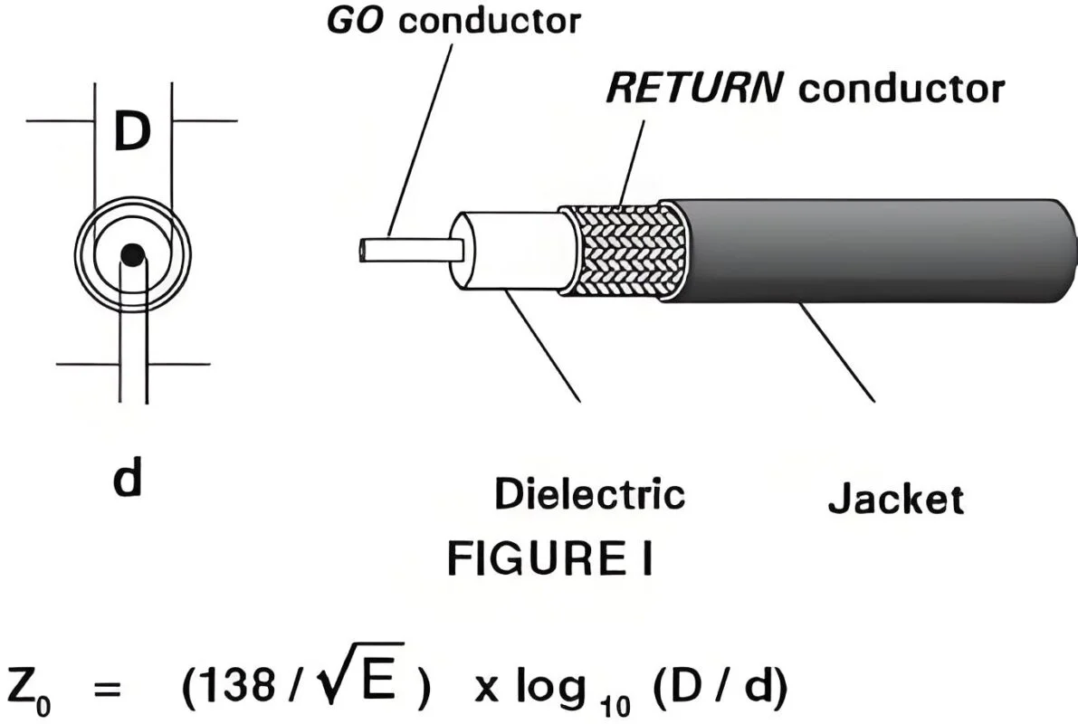
A coaxial cable uses a center conductor, dielectric, outer conductor or shield, and protective jacket arranged around a common axis. The geometry guides the electromagnetic field and establishes characteristic impedance. The connector must continue the cable geometry closely enough for the intended frequency range.
| Construction element | Why it matters in these applications |
|---|---|
| Center conductor | Influences resistance, loss, flexibility, current, plating, and termination |
| Dielectric | Influences impedance, velocity, attenuation, phase, temperature, and crush behavior |
| Outer conductor | Provides the return path and shielding; termination affects leakage and EMC |
| Jacket or protection | Controls handling, fluids, cleaning, abrasion, UV, temperature, and routing |
| Connector transition | Can introduce reflections, loss, phase change, leakage, and mechanical stress |
Shielding reduces coupling when the cable, connectors, equipment bonding, and installation are designed together. No cable alone guarantees immunity from interference, diagnostic performance, radio coverage, or regulatory compliance.
Impedance and Return Loss
Many RF and radio systems use nominal 50-ohm components, while some video, distribution, and instrumentation systems use 75-ohm components. The required impedance comes from the source, load, protocol, and connector system. Mechanical compatibility between connectors is not proof of electrical compatibility.
| Requirement | What to specify |
|---|---|
| Nominal impedance | 50 ohms, 75 ohms, or the value defined by the equipment |
| Return loss or VSWR | Frequency range, calibration, reference plane, fixture, and acceptance limit |
| Connector version | Exact series, impedance variant, cable group, gender, and orientation |
| Adapters and transitions | Part numbers, frequency rating, loss, impedance, and installation condition |
| Temperature condition | Operating range and any phase or impedance change limit |
For compact RF modules and higher-frequency designs, the custom RF cable assembly page provides a related assembly perspective. The current component and equipment datasheets should control exact frequency and impedance limits.
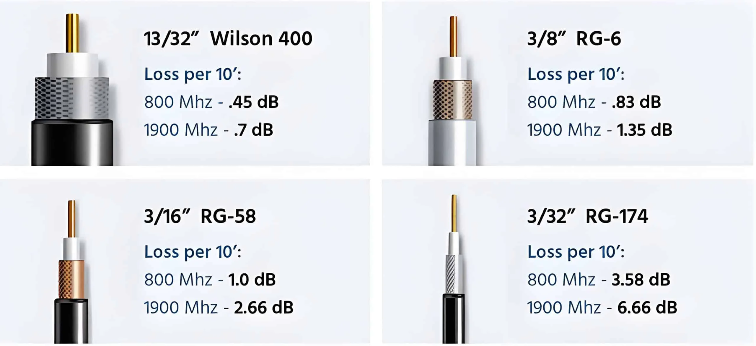
Frequency, Bandwidth, and Attenuation
5G and medical systems can use different frequency bands and signal architectures. The cable must be evaluated across the actual band, including harmonics, modulation, pulse edges, and any adjacent-band interference that matters to the system.
Insertion Loss
Insertion loss depends on cable length, conductor and dielectric materials, frequency, temperature, connector transitions, bends, and manufacturing variation. A short-cable value cannot be treated as a universal result for a longer installed assembly.
Return Loss
Return loss describes how much energy is reflected by impedance discontinuities. Connector launch geometry, damaged dielectric, adapters, incorrect cable groups, and mixed impedances can all affect the result.
Phase and Delay
Multi-antenna, beamforming, synchronized measurement, and imaging channels may require controlled length or phase. Define the frequency, temperature, cable length, connector configuration, reference plane, and matching tolerance before selecting a cable.
Noise and Crosstalk
Coaxial shielding can reduce external coupling, but noise may enter through connector shells, power supplies, enclosure apertures, grounding paths, or adjacent cables. Measure the installed system in representative operating modes when EMC risk is important.
5G Coaxial Cable Requirements
5G equipment design can include antenna feeders, radio-unit jumpers, internal module interconnects, test cables, and compact board-to-board or board-to-antenna connections. These locations have different loss, phase, mechanical, and environmental priorities.
Radio and Antenna Feeders
Outdoor or equipment-rack feeders require a complete loss budget, impedance match, connector sealing, grounding, UV and temperature evidence, bend control, and installation support. Large low-loss cable may reduce attenuation but can increase diameter, weight, bend radius, connector size, and installation effort.
Compact RF Module Connections
Internal RF jumpers may prioritize small diameter, low mass, controlled phase, connector retention, assembly access, and thermal behavior. A miniature coaxial cable can be convenient to route but may have different attenuation and handling limits from a larger flexible cable.
Test and Calibration Connections
Test cables become part of the measurement path. The design should control connectors, adapters, calibration plane, cable movement, bend condition, phase stability, and replacement criteria. A general-purpose patch lead should not be assumed suitable for a precision measurement without evidence.
For BNC-specific connector variants, use the BNC cable guide. Keep the industrial RF loss, power, motion, and environmental requirements in the project specification.
Medical Equipment Coaxial Cable Requirements
Medical equipment requirements depend on intended use, market, equipment classification, patient or operator contact, cleaning and disinfection, sample or reagent exposure, risk management, EMC, insulation, leakage, and the complete device architecture. A coaxial cable assembly does not independently establish compliance or diagnostic accuracy.
Imaging and Sensor Modules
Imaging and sensor cables may need stable signal behavior, low leakage, controlled flexing, compact routing, connector retention, cleaning compatibility, and reliable service access. The exact imaging modality, signal path, equipment location, and manufacturer requirements should be documented.
Cleaning and Disinfection
Identify whether the cable is wiped, immersed, exposed to a disinfectant, sterilized, or isolated from the cleaning zone. Record the chemical, concentration, temperature, exposure time, drying process, and number of expected service events. Do not apply a film or jacket rating to the complete assembly without representative evidence.
Patient, User, Sample, and Reagent Boundaries
These boundaries create different design and evidence needs. Patient-contact, user-contact, sample-contact, and internal equipment cables should not be treated as one category. The system owner must define materials, cleaning, biocompatibility, insulation, risk controls, and applicable standards for the complete device.
Medical Diagnostic Equipment
Some IVD and laboratory analyzers use coaxial or related cable structures for sensors, imaging, motors, or internal signals. The IVD equipment cable assembly guide covers instrument zones, cleaning boundaries, EMC, connectors, motion, traceability, and validation.
For differential video connections in medical or industrial equipment, review the medical and industrial DVI cable guide. A DVI or coaxial cable choice should follow the actual equipment interface, not a general medical label.
Coaxial Cable Families for 5G and Medical Equipment
| Family or construction | Useful starting point | Important limits to verify |
|---|---|---|
| RG-style flexible coax | Common equipment, RF, video, and test interconnects | Exact impedance, loss, shield, jacket, cable group, and temperature |
| Low-loss flexible coax | Longer RF paths or tighter loss budgets | Diameter, weight, bend radius, connectors, power, and environmental fit |
| Micro-coax | Compact internal modules and dense routing | Attenuation, handling, connector retention, tooling, and repair access |
| Semi-rigid coax | Stable formed internal RF paths | Forming, rework, minimum bend, connector launch, and mounting |
| Conformable coax | Shaped RF paths with more installation flexibility | Forming process, repeated motion, phase behavior, outer-conductor damage |
| Specialized low-outgassing or non-magnetic constructions | Equipment zones with material, vacuum, magnetic, or contamination limits | Exact material identity, evidence, system location, and OEM requirements |
RG names and marketing terms are not substitutes for a current manufacturer datasheet. The custom interconnect product options can be reviewed after the electrical, mechanical, and environmental requirements are defined.
Connector and Strain-Relief Selection
Select the connector from the mating part, impedance, frequency, cable diameter, mounting, environment, service access, and assembly process. Options may include BNC, SMA, N-type, TNC, micro-coax, board connectors, bulkheads, panel jacks, or proprietary equipment interfaces.
| Connector decision | Questions to confirm |
|---|---|
| Electrical interface | Impedance, frequency, loss, return loss, power, voltage, phase |
| Cable compatibility | Exact cable group, diameter, dielectric, shield, contact, ferrule, tooling |
| Mechanical interface | Keying, gender, orientation, mounting, coupling, retention, access |
| Environment | Temperature, fluids, cleaning, UV, vibration, ingress, magnetic restrictions |
| Service | Replacement, repair, mating, labeling, protective caps, inspection interval |
Strain relief should transfer handling and bending loads away from the contact and cable preparation area. Boots, clamps, backshells, heat shrink, potting, and overmolding each have different service and sealing implications. An overmolded cable assembly may help when resin, jacket, connector, mold, and adhesion are compatible, but the complete mated configuration still requires validation.
EMC and Grounding for Sensitive Systems
EMC performance depends on cable construction and the equipment installation. Review shield continuity, connector shell bonding, chassis entry, enclosure apertures, power routing, common-mode currents, grounding, and nearby switching sources.
- Define whether the shield bonds to chassis, signal reference, both, or a controlled network.
- Control shield termination through bulkheads, adapters, and overmold transitions.
- Separate sensitive RF or sensor paths from high-current switching circuits where required.
- Test with representative equipment modes, not only an unpowered bench.
- Document the test setup so results can be interpreted and repeated.
For mixed power, audio, video, RF, and control assemblies, review the industrial AV cable assembly design guide.
Specification Checklist for a Custom 5G or Medical Coaxial Assembly
| Specification area | Information to provide |
|---|---|
| Application | Equipment, signal path, zone, intended use, safety relevance, market |
| Frequency | Operating band, bandwidth, harmonics, modulation or pulse requirements |
| Impedance | Nominal value for source, cable, connectors, adapters, and load |
| Electrical limits | Attenuation, insertion loss, return loss, VSWR, phase, delay, shielding, power |
| Mechanical layout | Length, tolerance, bend, flexing, torsion, routing, branches, service loop |
| Materials | Conductor, dielectric, shield, jacket, sleeve, labels, restricted substances |
| Environment | Temperature, vibration, fluids, cleaning, UV, ingress, magnetic or contamination limits |
| Connectors | Exact part numbers, cable group, orientation, mating parts, sealing, mounting |
| Validation | Methods, fixtures, calibration, frequency, reference plane, limits, samples, report |
| Change control | Drawing revision, approved substitutions, traceability, requalification, notification |
Use the customized cable development process to move from requirements and drawing review to sample approval and production release. A supplier should not be asked to infer medical or 5G requirements from a product name alone.
Prototype and Validation Plan
A prototype should confirm connector fit, routing, length, flexing, labels, cleaning access, and the electrical measurements that matter to the application. A prototype cable assembly can expose installation and interface risks before final tooling or production release.
Project-dependent validation may include:
- Part-number, drawing, visual, dimensional, and workmanship inspection.
- Continuity, shorts, conductor resistance, and shield-bond checks.
- Impedance, insertion loss, return loss, VSWR, phase, or delay over the defined band.
- Functional testing with representative radio, instrument, imaging, or analyzer equipment.
- Flex, torsion, vibration, pull, temperature, fluid, cleaning, UV, ingress, or magnetic-environment tests when applicable.
- Post-test electrical and mechanical inspection using defined acceptance criteria.
- Documentation review for materials, traceability, change control, and packaging.
Qualification and production acceptance are different activities. State the sample, method, condition, equipment, calibration, frequency, reference plane, limit, and report format for each test.
Manufacturing and Quality Evidence
Quality controls for a coaxial assembly may include cable and connector part verification, controlled strip dimensions, dielectric protection, shield preparation, contact attachment, torque, cleanliness, strain relief, labels, continuity, and interface-specific RF testing. The exact controls should follow the released drawing and risk assessment.
Review the cable assembly quality approach and request project-specific evidence such as inspection formats, equipment records, calibration information, material data, and test reports with methods and acceptance limits. A broad certification statement cannot replace product-specific evidence.
Common 5G and Medical Coaxial Cable Problems
| Observed issue | Possible causes | Useful investigation |
|---|---|---|
| Excessive signal loss | Wrong cable, excessive length, connector transition, temperature, damaged dielectric | Complete-channel loss measurement, part verification, routing inspection |
| High reflection or VSWR | Impedance mismatch, connector launch, adapter, poor contact, bend damage | Return-loss or TDR test with controlled reference planes |
| Intermittent operation | Micro-coax movement, connector retention, conductor fracture, vibration | Dynamic inspection, motion test, connector and strain-relief review |
| EMC or noise problem | Shield discontinuity, grounding path, enclosure entry, nearby switching source | Shield and bonding review, representative equipment-mode test |
| Cleaning or fluid damage | Material incompatibility, seal damage, exposure beyond evidence | Fluid identification, exposure history, material and seal inspection |
| Medical equipment fault | Cable, connector, equipment, software, grounding, or system integration issue | Preserve evidence and diagnose the complete system before replacement |
5G and Medical Coaxial Cable FAQ
Are 5G coaxial cables different from ordinary RF coaxial cables?
They may use familiar RF constructions, but the required frequency band, loss, phase, connector, routing, power, and environmental conditions are defined by the specific radio or antenna system. A 5G label does not identify one universal cable.
Can the same coaxial cable be used in 5G and medical equipment?
Sometimes a cable family may be suitable for both, but suitability depends on interface, frequency, materials, cleaning, magnetic or EMC restrictions, mechanical use, intended application, and evidence requirements. The equipment owner must approve the complete design.
What impedance is used for medical coaxial cables?
There is no single medical impedance. Use the equipment and interface specification. Some systems use 50-ohm components, some use 75-ohm components, and other specialized architectures may apply.
Does shielding guarantee EMC compliance?
No. EMC depends on cable, connector termination, chassis bonding, routing, enclosure, power system, grounding, equipment modes, and test setup. The complete device must be evaluated against its applicable requirements.
Can a coaxial cable be sterilized or disinfected?
Only when the complete assembly and its materials are qualified for the stated method. Identify the chemical or process, exposure conditions, mating state, drying, and acceptance criteria. Do not transfer a film or jacket rating to the finished cable without evidence.
What tests should be requested for a custom medical or 5G coaxial cable?
Specify the tests needed for the project. They may include dimensions, workmanship, continuity, impedance, insertion loss, return loss, VSWR, phase, functional operation, flexing, vibration, temperature, cleaning, fluid, ingress, or other application-specific tests.
Can a cable assembly alone make a medical device compliant?
No. Compliance depends on the complete device, intended use, risk management, materials, electronics, insulation, EMC, software, installation, applicable standards, and final verification. The cable contributes evidence for its assigned requirements.
Request a 5G or Medical Coaxial Cable Review
Send the equipment interface, operating band, impedance, loss or phase limits, cable length, connector part numbers, routing, materials, cleaning or environmental conditions, and validation criteria. Contact WIRES for a project-specific coaxial cable assembly review.