BNC Cables: The Ultimate Guide
Get a clear look at the technical specs of BNC cables used in industrial gear and high-frequency security systems.
WIRES brings you this comprehensive guide covering connector structures, impedance matching, and precision wiring to ensure zero-error signal runs.
As a professional cable assembly manufacturer, WIRES maps out everything from basic plug styles to advanced factory assembly standards.
What Is a BNC Cable?
1. BNC Cable Structure
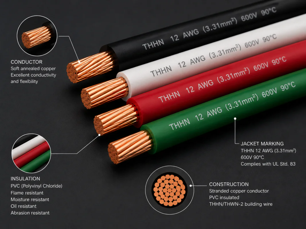
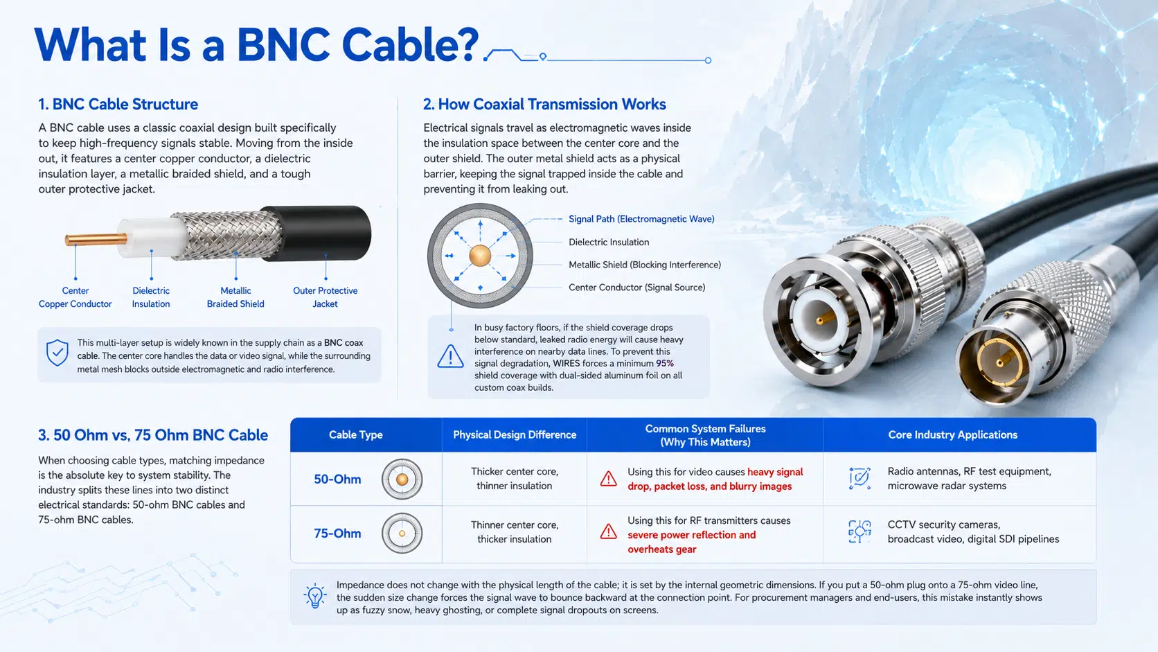
A BNC cable uses a classic coaxial design built specifically to keep high-frequency signals stable. Moving from the inside out, it features a center copper conductor, a dielectric insulation layer, a metallic braided shield, and a tough outer protective jacket.
This multi-layer setup is widely known in the supply chain as a BNC coax cable. The center core handles the data or video signal, while the surrounding metal mesh blocks outside electromagnetic and radio interference.
2. How Coaxial Transmission Works
Electrical signals travel as electromagnetic waves inside the insulation space between the center core and the outer shield. The outer metal shield acts as a physical barrier, keeping the signal trapped inside the cable and preventing it from leaking out.
In busy factory floors, if the shield coverage drops below standard, leaked radio energy will cause heavy interference on nearby data lines. To prevent this signal degradation, WIRES forces a minimum 95% shield coverage with dual-sided aluminum foil on all custom coax builds.
3. 50 Ohm vs. 75 Ohm BNC Cable
When choosing cable types, matching impedance is the absolute key to system stability. The industry splits these lines into two distinct electrical standards: 50-ohm BNC cables and 75-ohm BNC cables.
| Cable Type | Physical Design Difference | Common System Failures (Why This Matters) | Core Industry Applications |
| 50-Ohm | Thicker center core, thinner insulation | Using this for video causes heavy signal drop, packet loss, and blurry images | Radio antennas, RF test equipment, microwave radar systems |
| 75-Ohm | Thinner center core, thicker insulation | Using this for RF transmitters causes severe power reflection and overheats gear | CCTV security cameras, broadcast video, digital SDI pipelines |
Impedance does not change with the physical length of the cable; it is set by the internal geometric dimensions. If you put a 50-ohm plug onto a 75-ohm video line, the sudden size change forces the signal wave to bounce backward at the connection point. For procurement managers and end-users, this mistake instantly shows up as fuzzy snow, heavy ghosting, or complete signal dropouts on screens.
What Is a BNC Connector?
1. Bayonet Locking Mechanism
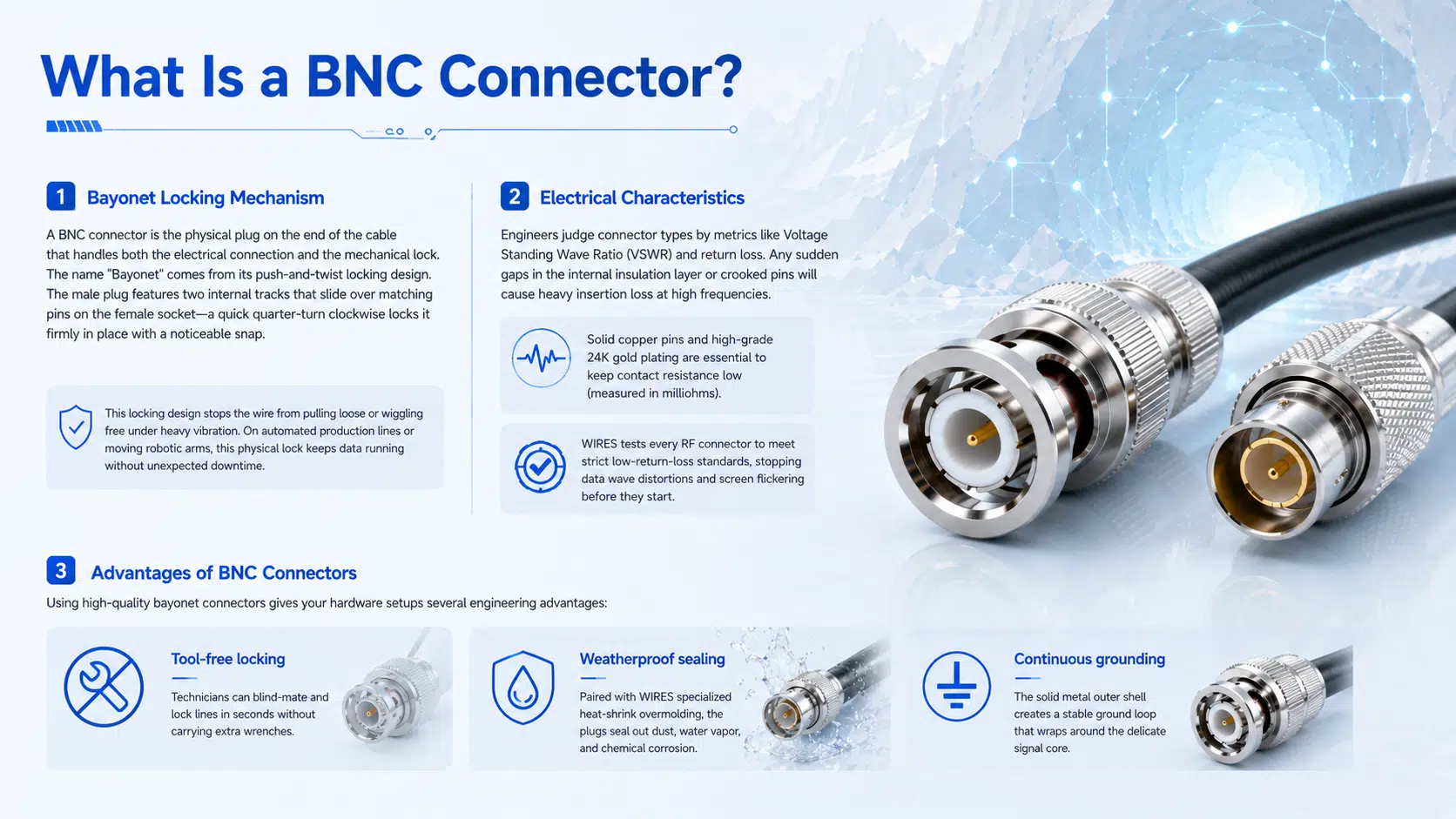
A BNC connector is the physical plug on the end of the cable that handles both the electrical connection and the mechanical lock. The name “Bayonet” comes from its push-and-twist locking design. The male plug features two internal tracks that slide over matching pins on the female socket—a quick quarter-turn clockwise locks it firmly in place with a noticeable snap.
This locking design stops the wire from pulling loose or wiggling free under heavy vibration. On automated production lines or moving robotic arms, this physical lock keeps data running without unexpected downtime.
2. Electrical Characteristics
Engineers judge connector types by metrics like Voltage Standing Wave Ratio (VSWR) and return loss. Any sudden gaps in the internal insulation layer or crooked pins will cause heavy insertion loss at high frequencies.
solid copper pins and high-grade 24K gold plating are essential to keep contact resistance low (measured in milliohms). WIRES tests every RF connector to meet strict low-return-loss standards, stopping data wave distortions and screen flickering before they start.
3. Advantages of BNC Connectors
Using high-quality bayonet connectors gives your hardware setups several engineering advantages:
Tool-free locking: Technicians can blind-mate and lock lines in seconds without carrying extra wrenches.
Weatherproof sealing: Paired with WIRES specialized heat-shrink overmolding, the plugs seal out dust, water vapor, and chemical corrosion.
Continuous grounding: The solid metal outer shell creates a stable ground loop that wraps around the delicate signal core.
RF and Video Connector Comparison
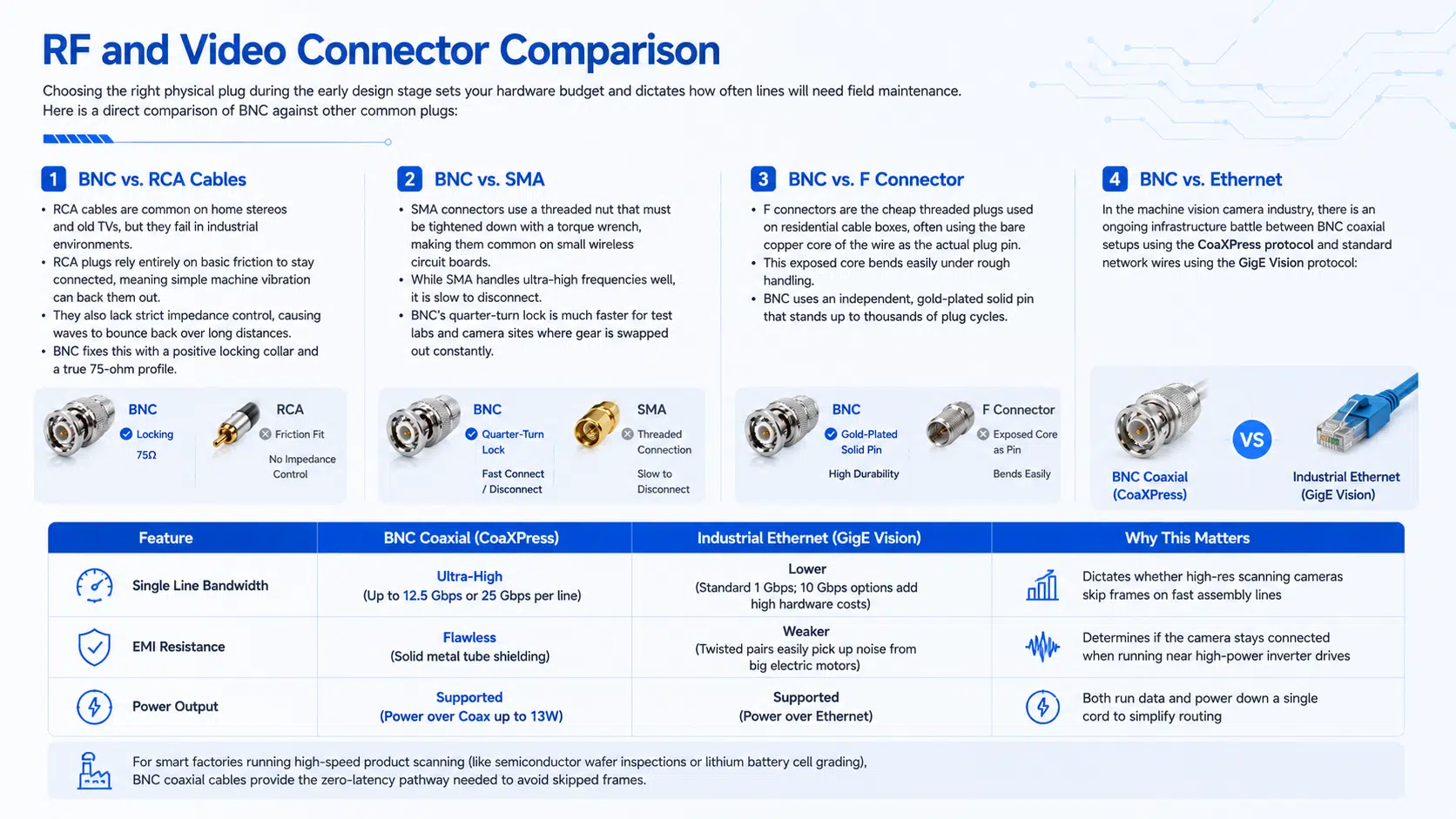
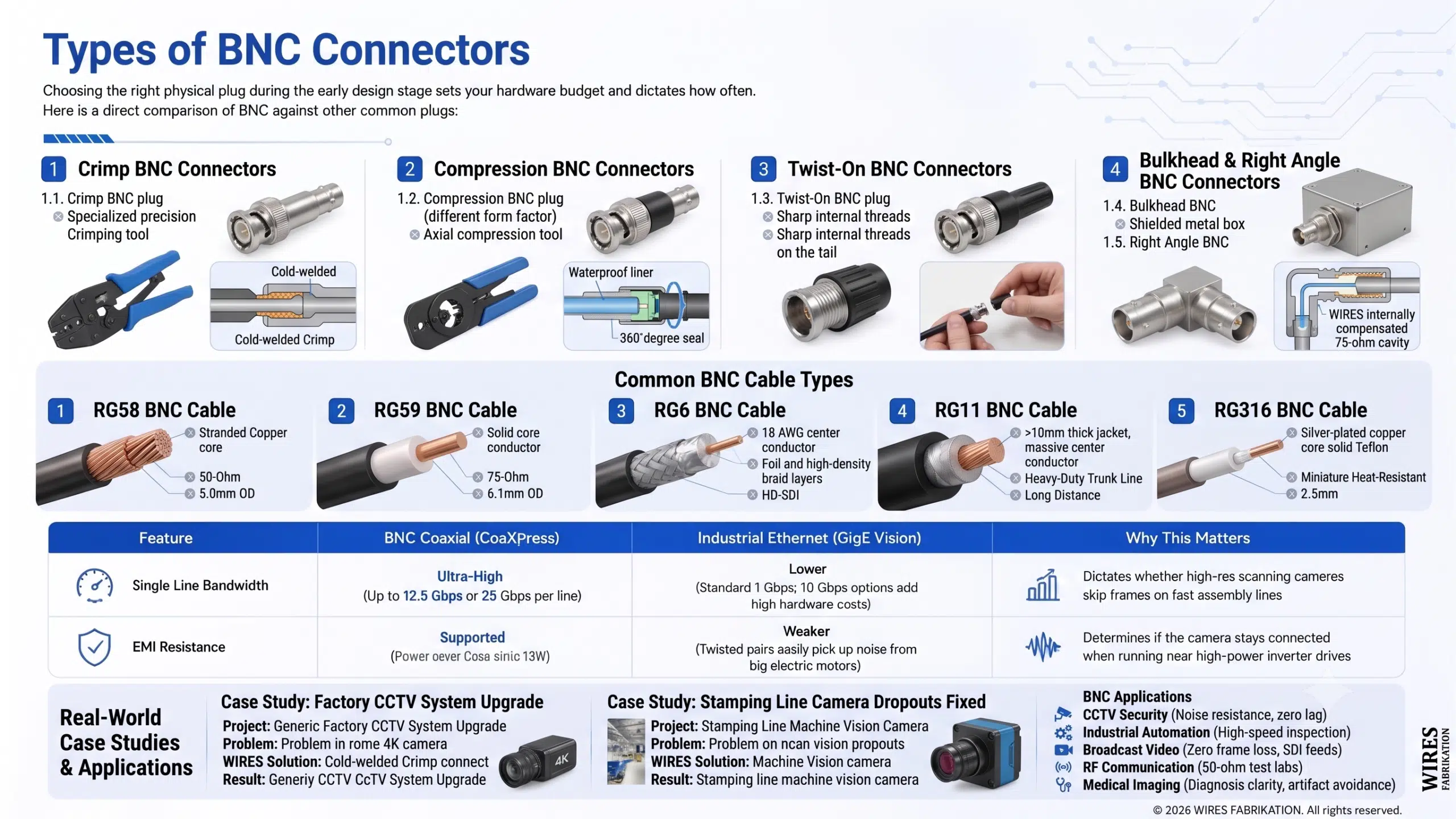
Choosing the right physical plug during the early design stage sets your hardware budget and dictates how often lines will need field maintenance. Here is a direct comparison of BNC against other common plugs:
1. BNC vs. RCA Cables
RCA cables are common on home stereos and old TVs, but they fail in industrial environments. RCA plugs rely entirely on basic friction to stay connected, meaning simple machine vibration can back them out. They also lack strict impedance control, causing waves to bounce back over long distances. BNC fixes this with a positive locking collar and a true 75-ohm profile.
2. BNC vs. SMA
SMA connectors use a threaded nut that must be tightened down with a torque wrench, making them common on small wireless circuit boards. While SMA handles ultra-high frequencies well, it is slow to disconnect. BNC’s quarter-turn lock is much faster for test labs and camera sites where gear is swapped out constantly.
3. BNC vs. F Connector
F connectors are the cheap threaded plugs used on residential cable boxes, often using the bare copper core of the wire as the actual plug pin. This exposed core bends easily under rough handling. BNC uses an independent, gold-plated solid pin that stands up to thousands of plug cycles.
4. BNC vs. Ethernet
In the machine vision camera industry, there is an ongoing infrastructure battle between BNC coaxial setups using the CoaXPress protocol and standard network wires using the GigE Vision protocol:
| Feature | BNC Coaxial (CoaXPress) | Industrial Ethernet (GigE Vision) | Why This Matters |
| Single Line Bandwidth | Ultra-High (Up to 12.5 Gbps or 25 Gbps per line) | Lower (Standard 1 Gbps; 10 Gbps options add high hardware costs) | Dictates whether high-res scanning cameras skip frames on fast assembly lines |
| EMI Resistance | Flawless (Solid metal tube shielding) | Weaker (Twisted pairs easily pick up noise from big electric motors) | Determines if the camera stays connected when running near high-power inverter drives |
| Power Output | Supported (Power over Coax up to 13W) | Supported (Power over Ethernet) | Both run data and power down a single cord to simplify routing |
For smart factories running high-speed product scanning (like semiconductor wafer inspections or lithium battery cell grading), BNC coaxial cables provide the zero-latency pathway needed to avoid skipped frames.
Types of BNC Connectors
1. Crimp BNC Connectors
Crimp plugs are the absolute standard for mass production and factory wire harness assembly. They consist of a main body, a center contact pin, and a separate outer metal sleeve called a ferrule. A precision crimping tool crushes the ferrule over the cable’s metal shield, creating a cold-welded mechanical bond that holds strong under high physical pull forces.
2. Compression BNC Connectors
Compression plugs are the default choice for outdoor runs and wet environments. They contain a waterproof internal liner that seals tight against the cable jacket when an axial compression tool squeezes the plug body together. This design offers a full 360-degree watertight seal that keeps moisture from wicking down the wire.
3. Twist-On BNC Connectors
Twist-on plugs allow for quick, tool-free field repairs. The tail of the connector features sharp internal threads that bite directly into the raw cable jacket and shielding as you twist it on by hand. While they lack the pull-out strength of a crimped wire, they are ideal for fast troubleshooting when crimping tools are unavailable.
4. Bulkhead BNC Connectors
Bulkhead plugs are designed to mount directly through cutouts on electrical enclosures, panel boxes, and server racks. They feature integrated threads and locking nuts to secure the plug to the panel wall. This allows internal signals to pass cleanly out of a shielded box while blocking stray electrical noise from the power supply.
5. Right Angle BNC Connectors
Right-angle plugs drop the traditional straight profile down to a tight 90-degree bend. This is necessary inside shallow equipment enclosures or when routing wires flat against a wall. To prevent the signal loss common in cheap bent plugs, WIRES molds an internally compensated cavity that keeps the path running at a true 75 ohms through the turn.
Common BNC Cable Types
1. RG58 BNC Cable: 50-Ohm RF Baseline
Within the cable types family, RG58 Cable is the standard choice for 50-ohm RF systems. It has an outer diameter of roughly 5.0mm and uses a stranded copper center core that makes the wire highly flexible. It is perfect for short jumps under 15 meters linking two-way radio antennas or benchtop test meters.
2. RG59 BNC Cable: Analog Video Gold Standard
RG59 Cable serves as the baseline 75-ohm wire for analog video and baseband signals. It features a solid copper or copper-clad steel center core inside a 6.1mm jacket. This balanced, cost-effective design makes them a common choice for legacy security monitor matrices and studio word-clock synchronization.
3. RG6 BNC Cable: High-Bandwidth Digital Mainstay
As modern systems moved to HD-SDI and 3G-SDI digital video, older RG59 wires began dropping data due to high-frequency attenuation. The heavier RG6 Cable steps up to an 18 AWG center conductor wrapped in multi-layer foil and high-density braid, making it the modern standard for long-distance digital video runs.
4. RG11 BNC Cable: Heavy-Duty Trunk Line
When your wire runs cross massive warehouse floors or run between buildings, even RG6 hits its distance limits. That is when you route heavy-duty RG11 Cable. At over 10mm thick, this stiff trunk line uses a massive center conductor to minimize signal loss over long, straight outdoor paths.
5. RG316 BNC Cable: Miniature Heat-Resistant Jumpers
On the opposite end of the scale, RG316 Cable is a micro-coaxial wire measuring just 2.5mm thick. To handle high data rates and extreme temperatures in tiny spaces, it utilizes a silver-plated copper core wrapped in a solid Teflon insulation layer. It is widely used for internal routing inside advanced medical imaging machines.
BNC Cable Applications and Real-World Case Studies
1. CCTV Security Systems
In commercial facility wiring, CCTV BNC Cables remain a massive infrastructure asset. While IP network cameras are common in new offices, analog high-definition coaxial systems are still the top choice for secure sites requiring physical data isolation, zero lag, and total noise resistance.
Real-World Case Study: Factory CCTV System Upgrade
The Project: An automotive assembly plant needed to upgrade their old security setup to clear 4K cameras without spending a massive budget on tearing out walls for new network lines.
The Problem: Running standard network lines meant starting from scratch, and the plant floor was filled with high-power electrical noise.
The WIRES Solution: We left the factory’s existing RG59 Cable in place and swapped out both ends with WIRES premium 75-ohm connectors mated to modern 4K analog cameras and DVRs.
The Result: Zero re-wiring costs. The plant got crisp 4K imagery while saving 75% of the estimated upgrade budget, and the coaxial shielding blocked out all factory floor motor interference.
2. Industrial Automation and Machine Vision
High-speed inspection cameras run 24/7 on automated assembly lines to catch product defects before they ship.
Real-World Case Study: Stamping Line Camera Dropouts Fixed
The Project: A components manufacturer added a rapid parts inspection line using high-res industrial cameras.
The Problem: The system suffered from random dropped frames and data errors, causing the entire line to halt unexpectedly. The cause was traced to standard camera lines running too close to high-power servo drives.
The WIRES Solution: We replaced the weak wires with custom-built, double-shielded RG6 Cable Assemblies using integrated mechanical locking plugs.
The Result: Data errors dropped by 99%, and unexpected assembly line shutdowns fell by 80%, saving the plant thousands in daily production losses.
3. Broadcast Video and Recording Studios
TV control rooms, production trucks, and recording spaces rely on Serial Digital Interface lines. Losing a single frame of video can ruin a live broadcast, so network data buffering is not an option. Premium BNC Cable Assemblies built with pristine plating and exact crimp tolerances handle up to 12G-SDI ultra-HD feeds, keeping multiple audio and video tracks perfectly synced down to the millisecond.
4. RF Communication and Radio Systems
Wireless networks, radio base stations, and test labs rely entirely on 50-ohm coaxial channels. Test engineers use these paths to route delicate radio frequencies straight into spectrum analyzers and oscilloscopes. Any small dimension errors inside the plug will bounce the power backward, risking damage to sensitive internal amplifier chips.
5. Medical Imaging Equipment
Advanced ultrasound scanners and MRI systems route weak electrical signals from handheld imaging probes back to the main processing computer. The consistency of the custom components directly impacts the contrast and clarity of the diagnostic image on the doctor’s screen, making precision wire manufacturing essential to avoid artifact spots.
How to Install a BNC Connector
1. Precision Crimp Method
Crimping is the industrial standard for building high-reliability wire harnesses that meet strict Class 3 manufacturing rules.
Step 1: Use a coaxial wire stripper to cleanly cut away the outer jacket and shield at the 1/4-inch mark without nicking the inner wires.
Step 2: Strip back the inner insulation layer at the next 1/4-inch mark to expose the clean center conductor.
Step 3: Slide the center contact pin over the conductor and lock it down using a pneumatic or calibrated hand crimping tool.
Step 4: Push the plug body over the core until the center pin clicks into place, sandwiching the outer metal shielding braid over the rear barrel of the plug.
Step 5: Slide the outer ferrule up over the braid and use the crimp tool to compress the metal sleeve. A calibrated pull-test ensures the mechanical bond exceeds industry standards.
2. Waterproof Compression Method
Compression fittings provide excellent long-term moisture protection for outdoor paths.
Step 1: Use a matched coaxial stripping blade to make a staggered cut through the jacket and insulation in a single motion.
Step 2: Fold the exposed outer shielding mesh back evenly over the outer jacket so it is perfectly symmetrical.
Step 3: Push the cable straight into the compression plug body until you feel the center pin seat inside the internal lock.
Step 4: Place the plug into a compression tool and squeeze the handle. This forces an internal plastic sleeve into the plug housing, creating a tight 360-degree environmental seal around the wire jacket.
3. Traditional Solder Method
Soldering is used for low-volume specialty medical lines or delicate laboratory calibration jumpers.
Step 1: Strip the wire to standard staggered dimensions and fold back the shielding mesh.
Step 2: Insert the exposed copper core fully into the solder pocket at the back of the center pin.
Step 3: Use a temperature-controlled soldering iron to make a fast, clean joint. The iron must touch the pin for no more than 2 to 3 seconds. If you apply heat for too long, the thermal energy will melt the internal Teflon insulation layer, ruining the cable’s concentricity and throwing off its impedance profile.
Purchasing Factors: BNC Cable Cost and Pricing Mechanisms
When managing cross-border procurement budgets for custom hardware projects, you need to understand the technical drivers behind BNC Cable Assemblies pricing:
Raw Cable Material: High-temp, silver-plated RG316 or heavy-duty RG11 trunk lines carry a significantly higher material cost than standard mass-produced RG59.
Connector Plating Grade: Plugs using thick 24K gold plating and integrated mechanical locks cost more upfront than basic commercial zinc-alloy plugs with thin nickel washes.
Shielding Coverage Level: Standard single-braid wires use roughly half the raw copper of a premium quad-shielded line featuring double-sided foil and dual high-density braids.
Custom Modification Requirements: Adding molded strain relief boots or specified polyurethane trailing jackets changes the manufacturing run time and tooling costs.
To get the best total cost of ownership for your hardware run and avoid costly field failures, contact our engineering team to get a detailed bill of materials and a competitive factory quotation for your custom requirements.
WIRES Digital Flexible Manufacturing and Custom Capabilities
As a dedicated wire harness manufacturer with 28 years of industry experience, WIRES builds strict quality controls into every single assembly step:
Design Review and DFM
When you submit your drawings or spec sheets, our engineering team runs a full check to verify bend radiuses and matching impedance profiles before production begins.
Rapid Prototyping
We run first-article samples through dedicated engineering lines, allowing your team to run physical fitment tests before committing to large volumes.
Calibrated Digital Crimping
Our factory production floor utilizes electronic crimp force monitors to ensure every single terminal pin is crushed to exact material tolerances for stable grounding.
Secondary Overmolding
We offer custom-tooling injection molding to encapsulate the rear of the plug, giving the cable assembly excellent strain relief and bend protection.
100% Vector Network Analyzer Testing
We do not spot-check high-frequency lines. Every single data and RF cable assembly faces full electrical testing for continuity, shorts, and insulation resistance. For high-speed lines, we connect every unit to a VNA to verify real-world VSWR and insertion loss limits.
Certified Manufacturing
Our production facilities run under ISO 9001, ISO 14001, and IATF 16949 quality controls, with assembly staff trained to IPC-WHMA-A-620 Class 3 standards. Every material lot holds full UL safety ratings and meets RoHS international environmental compliance.

Frequently Asked Questions About BNC Cables
Q1: What is a BNC cable used for?
A BNC Cable is a high-reliability coaxial line used to carry high-frequency electrical signals with minimal distortion. You will find them everywhere from analog HD security cameras and broadcast television control rooms to laboratory test gear like oscilloscopes, radio antenna arrays, and automated factory machine vision cameras.
Q2: What is the difference between 50-ohm and 75-ohm BNC cables?
The difference comes down to internal geometric dimensions, which set the cable’s characteristic impedance. A 50-ohm coaxial line, like standard RG58 with a thick 0.82 mm² stranded core, is optimized to carry raw radio frequency power efficiently without arcing. A 75-ohm line, like RG59 or RG6, is tuned to preserve the precise shape and timing of high-frequency video and image waves over long distances.
Q3: Can I use a 50-ohm BNC connector on a 75-ohm cable?
No. While they share the exact same outer bayonet lock shell and can physically snap together, the internal dimensions of their insulation layers are different. Squeezing a 50-ohm plug onto a 75-ohm wire creates a physical bottleneck that forces high-frequency signals to bounce backward. At frequencies past 1 GHz, this mismatch creates a 3 dB to 6 dB return loss, showing up as double edges, fuzzy screens, or random data dropouts.
Q4: Can BNC coaxial cables carry modern 4K ultra-HD video?
Yes. High-grade coaxial lines handle dense ultra-HD video streams with ease. In professional broadcast studios and live production vans, premium 75-ohm cables built to 12G-SDI standards carry raw, uncompressed 4K video at 60Hz over a single line without packet buffering lag.
Q5: In factory automation, does a BNC cable run digital or analog signals?
It handles both cleanly. While historically used for analog camera feeds and old oscilloscope lines, modern industrial systems run pure high-speed digital data through them. For instance, the CoaXPress protocol used by rapid factory inspection cameras runs digital image streams at up to 12.5 Gbps per single channel over standard BNC coaxial lines.
Q6: Does physical cable length impact BNC signal quality?
Yes. High-frequency signals lose strength linearly the further they travel down a wire. For example, a standard RG59 wire running a 1 GHz signal drops roughly 30 dB to 40 dB of signal power for every 100 meters of distance. If your run is too long, the signal falls below the equipment’s reading threshold, requiring you to step up to a thicker, low-loss RG6 or RG11 wire.
Q7: Can BNC cable assemblies and connectors handle outdoor environments?
Standard commercial BNC plugs will rust and leak if exposed to rain. However, if you specify heavy-duty compression connectors featuring internal Teflon seals, pair them with UV-rated outer jackets, and add secondary overmolding, the finished cable assembly will run reliably through outdoor rain, sun, and mild chemical exposure.
Q8: What is the maximum operating frequency of a BNC connector?
Standard industrial bayonet BNC plugs are designed to operate safely at frequencies under 4 GHz. Past this point, the minor mechanical gaps in the push-and-twist locking style begin causing high insertion loss and signal leakage. For ultra-high microwave projects running from 10 GHz to 18 GHz, engineers switch to threaded SMA type connectors.
Q9: Why is BNC preferred over a standard RCA Cables for commercial gear?
BNC outclasses standard RCA Cables in both mechanical strength and electrical consistency. The bayonet lock keeps BNC lines from being accidentally pulled out or vibrated loose during operation. Electrically, BNC connectors are precision-machined to maintain a true 50-ohm or 75-ohm profile, whereas common RCA plugs cause wide impedance variations that distort delicate signals.
Q10: What specific raw wires are commonly built into BNC cable assemblies?
The type of wire depends entirely on your project’s space and frequency needs. The most common supply chain standards include ultra-small RG316 (ideal for tight internal medical wiring), flexible RG58 (the 50-ohm RF baseline), standard RG59 (the baseband analog video wire), and heavier, low-loss RG6 or RG11 lines for long-distance digital data runs.
Q11: What exactly is an RG59 BNC cable?
An RG59 BNC cable is a 75-ohm coaxial assembly built with a 20 AWG solid copper or copper-clad steel center core. It balances a manageable outer thickness with solid low-attenuation performance at baseband video frequencies, making it a reliable infrastructure wire for security camera matrices and audio studio clock distribution.
Q12: What is the difference between RG59 and RG6 wires when choosing a BNC cable?
The main differences are center core thickness and shielding levels. RG6 features a thicker center core (typically 18 AWG compared to RG59’s thinner 20 AWG core) and utilizes multi-layer foil and denser wire braiding. This heavier construction allows RG6 to carry high-frequency digital signals much further than RG59 before encountering signal loss.
Q13: How can a technician quickly test a BNC cable for faults in the field?
The fastest method is a basic continuity and resistance test using a standard digital multimeter set to ohms. First, unplug both ends of the cable. Touch the meter probes to the center pin and outer metal shell of the same plug; the reading should show infinite resistance (indicating no internal shorts). Next, check the resistance from center pin to center pin across the length of the wire; it should read close to zero ohms (typically under 0.5 ohms).
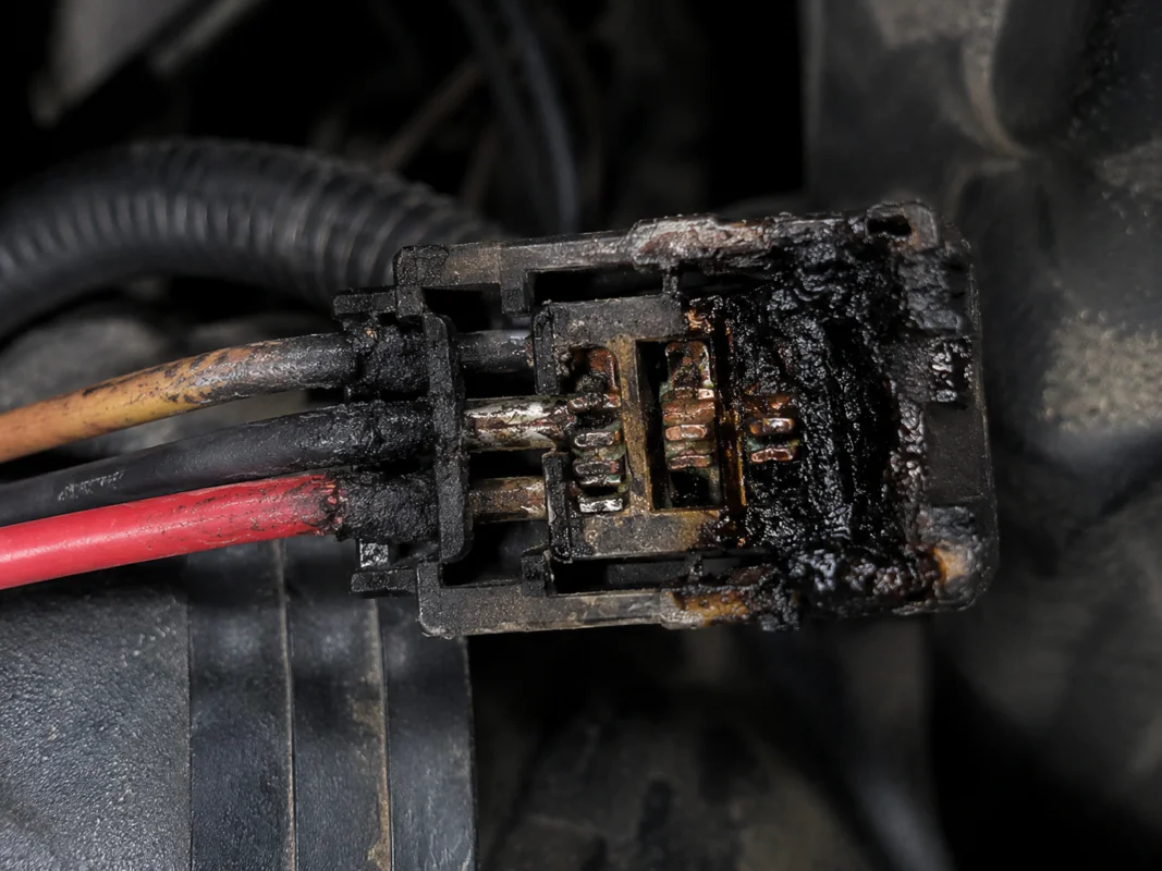
Q14: Why does my BNC security camera screen show moving lines or no signal?
This is typically caused by one of three physical layer issues: first, the wire may be using a cheap twist-on plug that wiggled loose, spiking contact resistance past 50 milliohms; second, the line may be bundled right next to a 380V factory power line, bleeding electrical noise through a weak shield; third, a 50-ohm wire may have been mistakenly swapped into a 75-ohm video line, causing heavy wave reflection.
Q15: What is the typical Minimum Order Quantity (MOQ) when ordering custom BNC wire harnesses?
Because setting up automated stripping machines and pneumatic crimp dies requires time and tooling calibrations, large commercial factories often require minimum runs of several thousand units. However, WIRES utilizes a flexible digital manufacturing setup that supports small-batch OEM runs down to 50 or 100 pieces, allowing engineering teams to get fully tested assemblies for early product validations without heavy upfront costs.
Conclusion
The evolution of BNC Cables and connectors is a continuous engineering effort to preserve signal integrity against electromagnetic noise, wave reflection, and physical wear. Understanding the clear performance gap between 50-ohm and 75-ohm paths, and enforcing strict crimping and assembly rules, is the foundation for keeping factory automation, security systems, and precision test lab meters running with zero unexpected downtime.
When your project demands custom coaxial lines that match exact electrical specs, choosing a manufacturer with deep validation capabilities is essential.
WIRES uses advanced Design-for-Manufacturability (DFM) Framework to supply high-shielding, high-pull-strength, and true-impedance BNC cable assemblies tailored for rugged commercial use. If your upcoming build faces tough operating environments or strict compliance standards, our engineering team is ready to evaluate your spec sheets and provide full physical-layer technical support.