Micro USB Cables: The Ultimate Guide to Making the Right Choice
With so many Micro USB cables on the market, how do you find the ones that perfectly match your equipment? For engineers and buyers working in high-reliability industrial or medical settings, picking the wrong cables frequently leads to signal drops, equipment reboots, or power shortages.
This guide covers everything you need to know about Micro USB cables so you can confidently choose the right ones for your specific applications.
Chapter 1: What are Micro USB Cables?
The Micro USB cable represents a miniature version of the USB 2.0 standard, introduced by the USB-IF to standardize connections across smaller portable devices, embedded systems, and industrial hardware.
1.1 Pinout and Key Functions
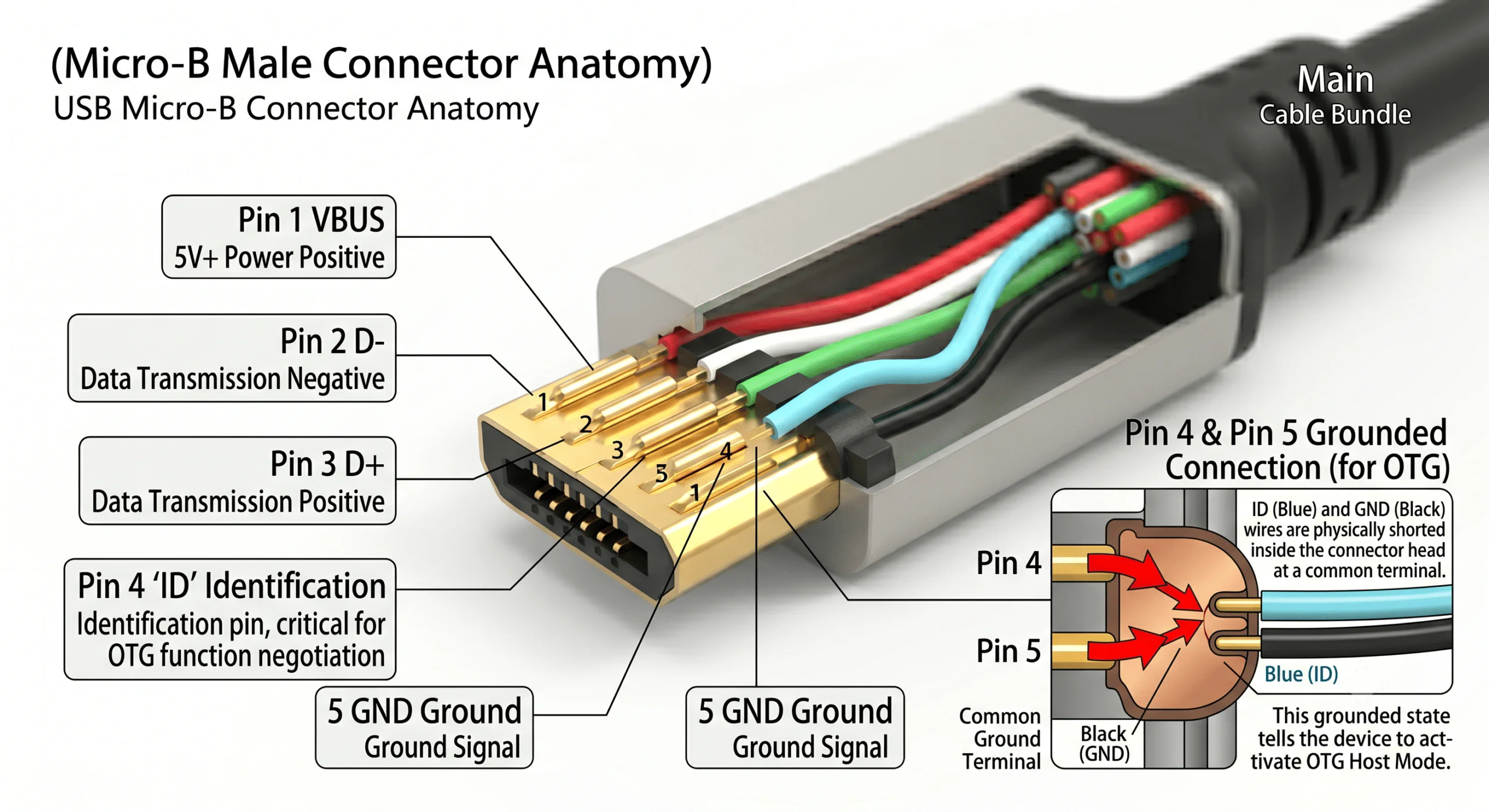
Standard USB 2.0 Micro USB cables contain 5 pins. The inclusion of a dedicated ID pin (Pin 4) is what separates it from traditional 4-pin USB Type-A connectors, enabling advanced device-to-device roles:
| Pin Number | Signal Name | Standard Wire Color | Description |
| Pin 1 | VBUS | Red | Power positive (typically 5V) |
| Pin 2 | D- | White | Data transmission differential signal (negative) |
| Pin 3 | D+ | Green | Data transmission differential signal (positive) |
| Pin 4 | ID | Floating / Grounded | OTG (On-The-Go) Host/Slave identification |
| Pin 5 | GND | Black | Power and signal ground |
Core Technical Point: When Pin 4 (ID pin) is shorted directly to Pin 5 (GND), the cable activates OTG Host mode. This allows industrial tablets or embedded boards to act as a master device and read USB drives, sensors, or communication modules directly without needing a PC host.
1.2 Mechanical Durability Design
Compared to older Mini USB setups, Micro USB cables move the flexible, wear-prone spring latches from the device socket to the cable plug. Because of this structural shift, the physical wear and tear from daily insertions happens to the inexpensive cable rather than the costly equipment motherboard, drastically reducing maintenance overhead.
Chapter 2: Micro USB Interface Types
Before selecting your cables, you must identify the exact physical Micro USB port layout on your hardware:
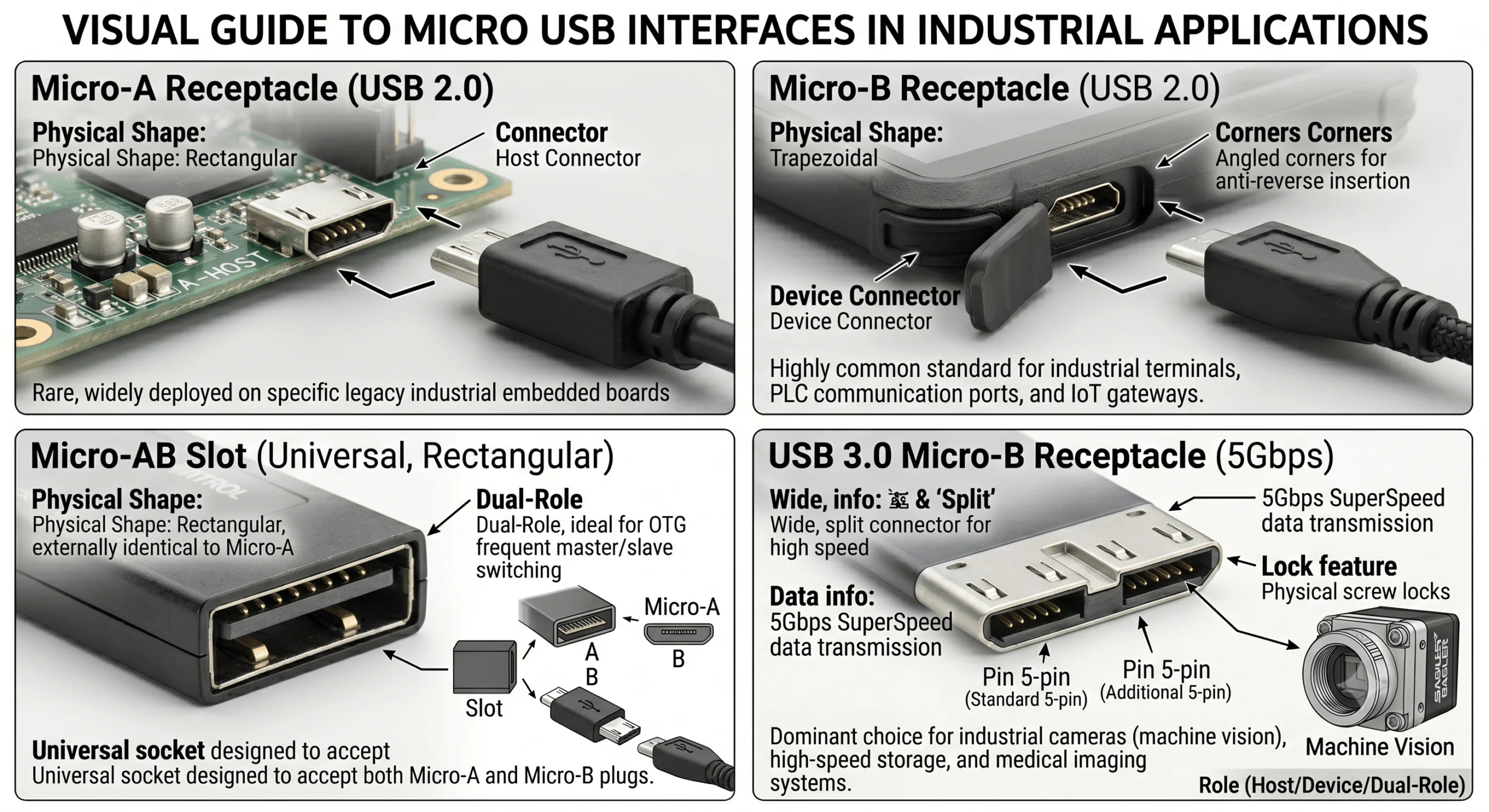
Micro-A Interface: Recognizable by its rectangular shape, typically used as a Host connector. It is rare today but still widely deployed on specific legacy industrial embedded boards.
Micro-B Interface: The highly common trapezoidal shape with distinct angled corners for anti-reverse (fool-proof) insertion. It is the standard choice for industrial smart terminals, PLC communication ports, and IoT gateways.
Micro-AB Slot: A universal, rectangular socket designed to accept both Micro-A and Micro-B plugs. It is ideal for control systems requiring frequent master/slave role switching.
USB 3.0 Micro-B Interface: A wide, 10-pin split connector designed for 5Gbps SuperSpeed data transfer. It is the dominant choice for industrial cameras (machine vision), high-speed storage, and medical imaging systems, and almost always features physical screw locks.
Chapter 3: Micro USB Cables Technical Classification and Industry Selection
In rigorous B2B environments, Micro USB cables differ heavily based on their internal wire gauge, shielding configuration, and outer jacket compounding.
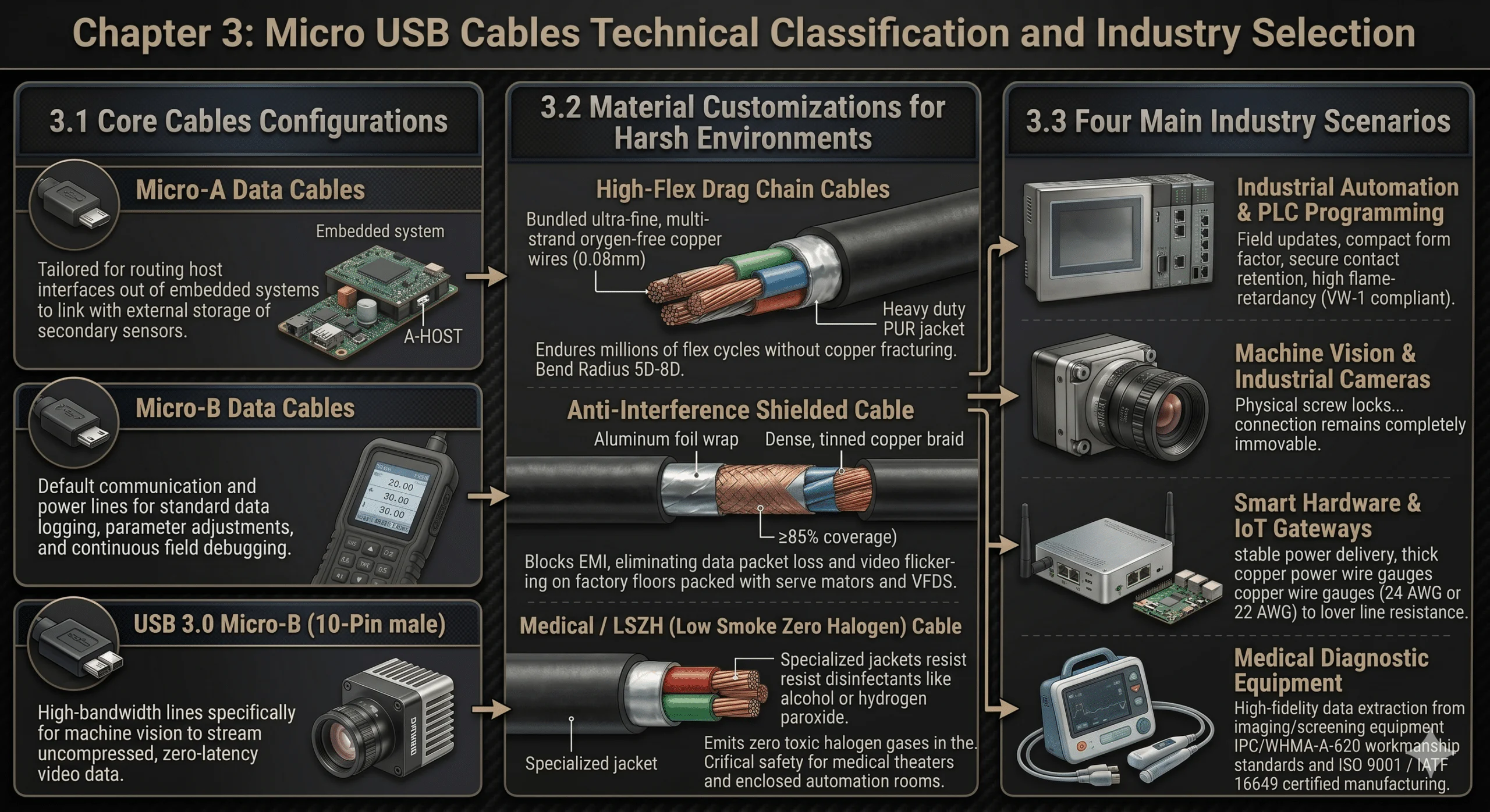
3.1 Core Cables Configurations
Micro-A Data Cables: Tailored for routing host interfaces out of embedded system enclosures to link with external storage or secondary sensors.
Micro-B Data Cables: The default communication and power lines used for standard data logging, parameter adjustments, and continuous field debugging.
USB 3.0 Cables (10-Pin): High-bandwidth lines engineered specifically for machine vision setups to stream uncompressed, zero-latency video data.
3.2 Material Customizations for Harsh Environments
High-Flex Drag Chain Cables: Built for the repetitive motion of robotic arms and pick-and-place slides. They utilize ultra-fine, multi-strand oxygen-free copper wires (e.g., 0.08mm) protected by a heavy-duty PUR (polyurethane) jacket. Featuring a bend radius of 5D to 8D, these cables endure millions of continuous flex cycles without copper fracturing.
Anti-Interference Shielded Cables: Indispensable for factory floors packed with high-frequency radiation from servo motors and variable frequency drives (VFDs). They feature an aluminum foil wrap combined with a dense, tinned copper braid (≥85% coverage) to block EMI, eliminating data packet loss and video flickering.
Medical / LSZH (Low Smoke Zero Halogen) Cables: Designed with specialized jackets that withstand aggressive medical disinfectants like alcohol or hydrogen peroxide. In case of fire, they emit zero toxic halogen gases, fulfilling crucial safety criteria for medical theaters and enclosed automation rooms.
3.3 Four Main Industry Scenarios
3.3.1 Industrial Automation & PLC Programming
Used daily for field updates and programming PLCs, HMIs, and smart meters. Deployed cables must favor a compact form factor, highly secure contact retention, and high flame-retardancy (such as VW-1 compliance).
3.3.2 Machine Vision & Industrial Cameras
High-speed inspection cameras experience severe, non-stop equipment vibration. These applications demand custom cables equipped with physical screw locks to ensure the data connection remains completely immovable.
3.3.3 Smart Hardware & IoT Gateways
For remote data hubs and single-board computers (SBCs), the primary concern is stable power delivery. Buyers must select cables with thick copper power wire gauges—specifically 24 AWG or 22 AWG—to lower line resistance and avoid the critical voltage drops that cause unexpected system reboots.
3.3.4 Medical Diagnostic Equipment
Used for high-fidelity data extraction from portable imaging and screening equipment. These cables must be manufactured in facilities adhering strictly to IPC/WHMA-A-620 workmanship standards and certified under ISO 9001 or IATF 16949 quality systems.
Chapter 4: Micro USB Specialized Cables Solutions
To conquer complex machine layouts, structural restrictions, or direct field interfacing, three specialized cable variations are widely implemented:
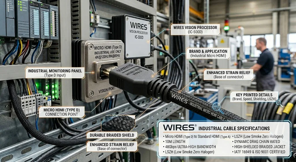
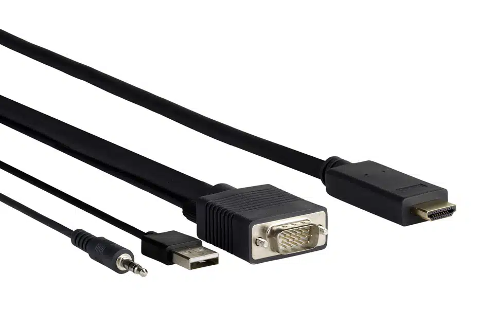
Micro USB to HDMI Cables: Engineered for micro-controllers or handheld instruments lacking an independent video port. By utilizing MHL technology, they output HD video directly through the Micro USB layout. WIRES embeds an internal, low-power digital converter chip directly inside the plug to ensure a zero-lag, clear display on external monitors.
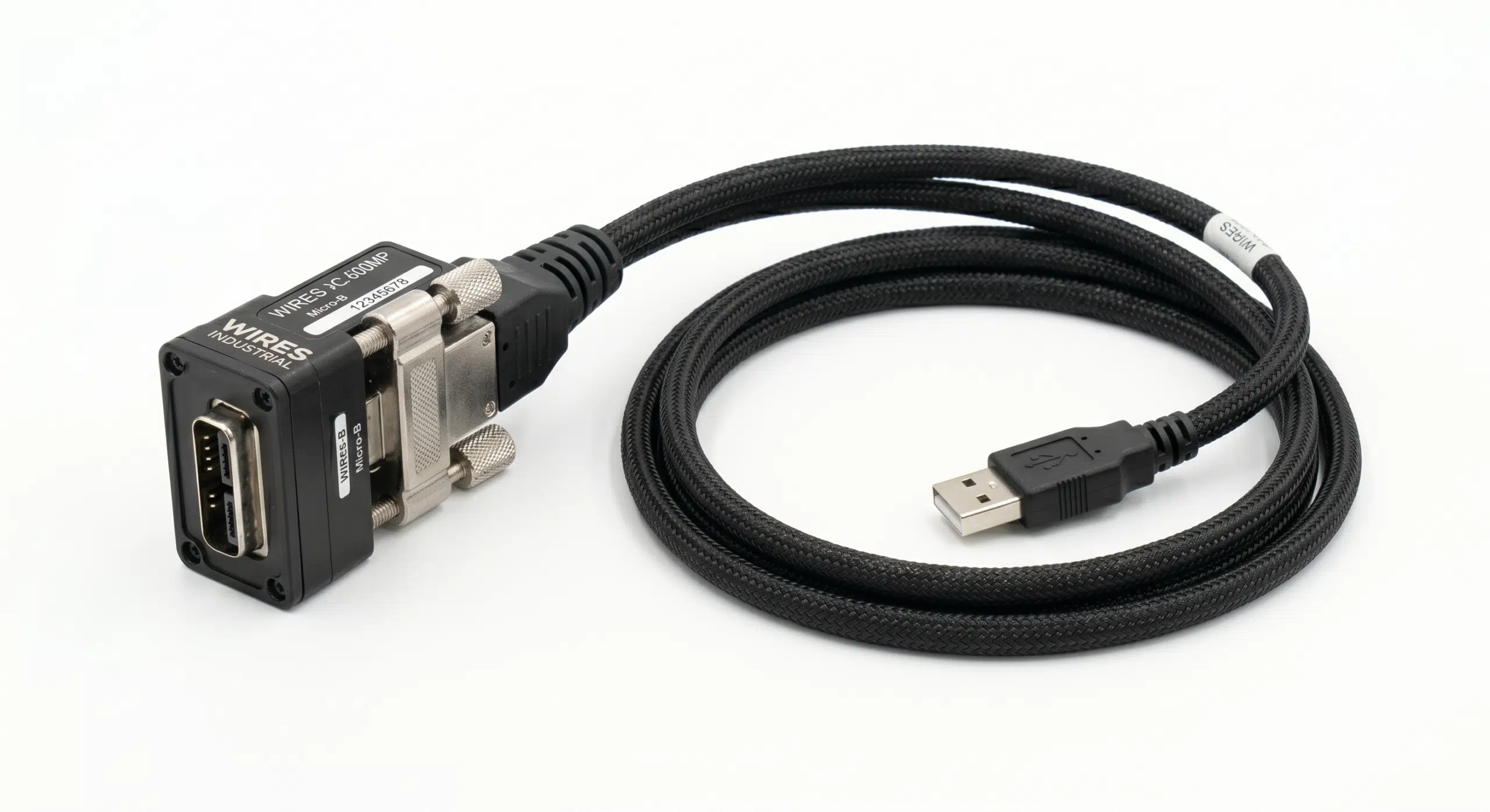
Micro USB Extension Cables: Used to extend hard-to-reach internal ports out to an accessible enclosure panel. These are frequently configured as panel-mount extensions featuring dual M3 locking screws. They are built with over-spec wire gauges to counteract the attenuation and voltage drop common over extended distances.
Micro USB to Micro USB Cables: Tailored for point-to-point data synchronization between two micro-interface devices (e.g., a field PDA reading an external diagnostic module). These are hardwired with Pin 4 and Pin 5 tied to ground on the host side, establishing an instant master-to-slave link without an intermediate computer.
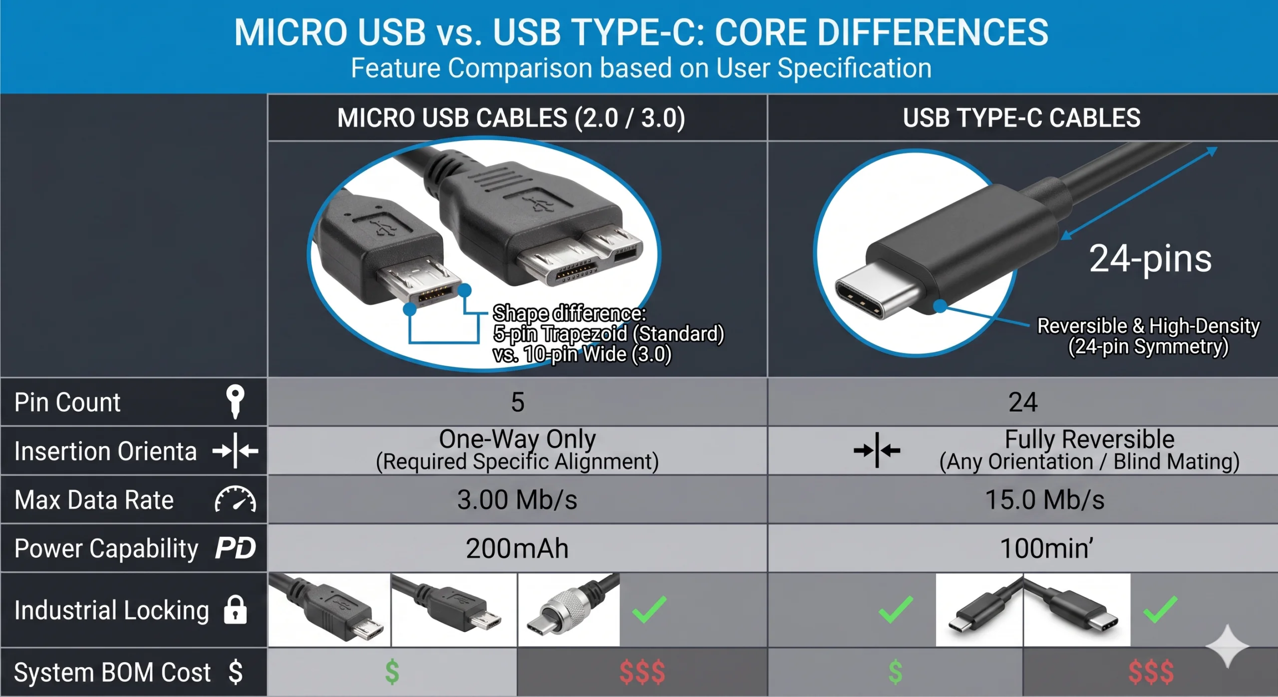
Chapter 5: Micro USB Cables vs. USB Type-C Core Differences
| Feature / Specification | Micro USB Cables (2.0 / 3.0) | USB Type-C Cables |
| Pin Count | 5 Pins (2.0) / 10 Pins (3.0) | 24 Pins |
| Insertion Style | One-way (trapezoidal layout) | Reversible (blind mating) |
| Max Data Rate | 480 Mbps (2.0) / 5 Gbps (3.0) | 10 Gbps / 20 Gbps / 40 Gbps+ |
| Power Capacity | Max 5V 2A (10W), up to 15W under protocols | 15W standard, up to 100W / 240W via Power Delivery |
| Industrial Locking | Highly mature; vast catalog of single/dual screw locks | Locking options exist, but dense pins make the assembly fragile |
| System BOM Cost | Extremely Low (massive savings on circuit design and port costs) | Higher (requires CC controllers, multi-layer PCBs, and protection) |
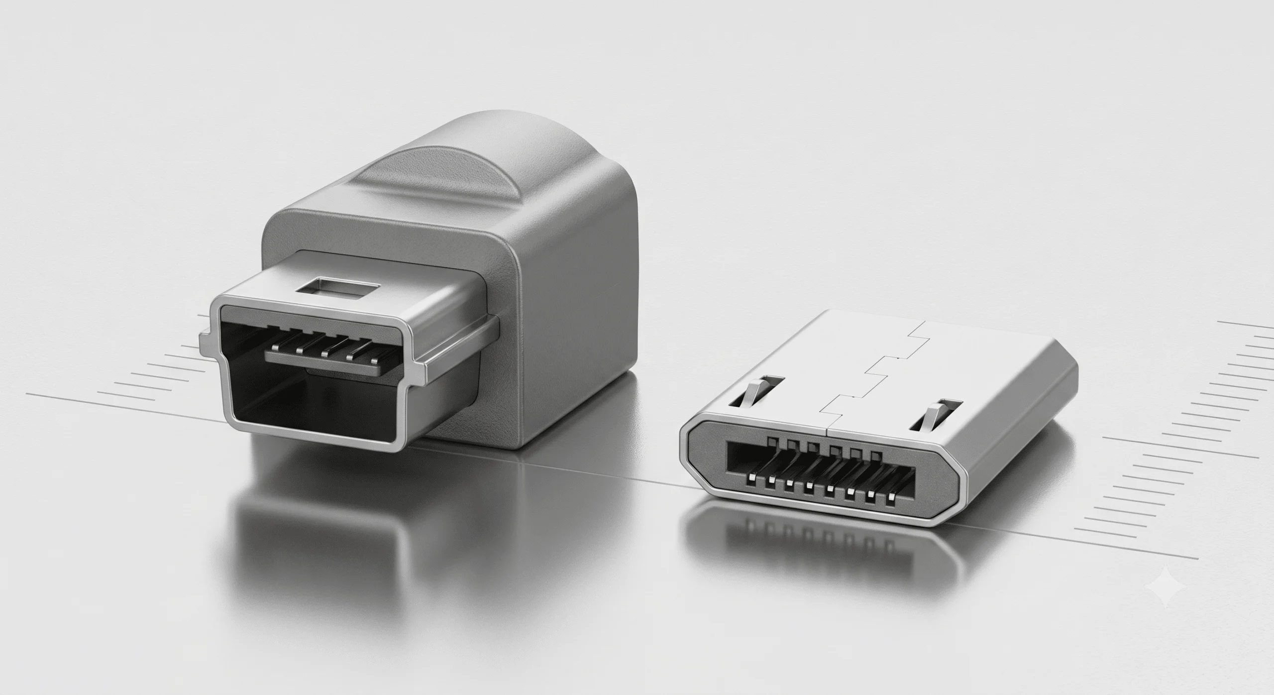
Chapter 6: Micro USB Cables vs. Mini USB Depth Comparison
[Mini USB Setup]  --> Spring clips inside the device port  --> Wear occurs on hardware --> Expensive repair
[Micro USB Setup] --> Spring clips inside the cable plug   --> Wear occurs on the cable --> Inexpensive swap
Lifespan Upgrade: Mini USB relies on spring clips mounted inside the actual device socket, meaning a worn-out clip results in a broken device board. Micro USB cables pull those spring tabs into the cable plug, ensuring physical wear happens on the disposable line. This design choice bumps the rated connection lifespan to 10,000 cycles.
Form & Function: Micro USB slashes the physical thickness of Mini USB by nearly 50% to accommodate modern, low-profile enclosures, while delivering native OTG peer-to-peer routing architecture.
Conclusion
Securing an optimal connection requires checking specific operational stress factors against your cable architecture:
For continuous machine travel, deploy high-flex drag chain cables.
For high-noise factory zones, isolate with dual-layer shielded cables (foil + braid).
For structural cabinets, streamline with panel-mount extension cables.
For voltage-sensitive power demands, strictly mandate 24 AWG or 22 AWG conductors.
As a veteran cable and wire harness manufacturer with 28 years of industry experience, WIRES builds assemblies fully compliant with IATF 16949 and IPC/WHMA-A-620 quality standards. From heavy-duty shielded lines to medical-grade layouts, we build the reliable connections that ensure your systems maintain maximum uptime.