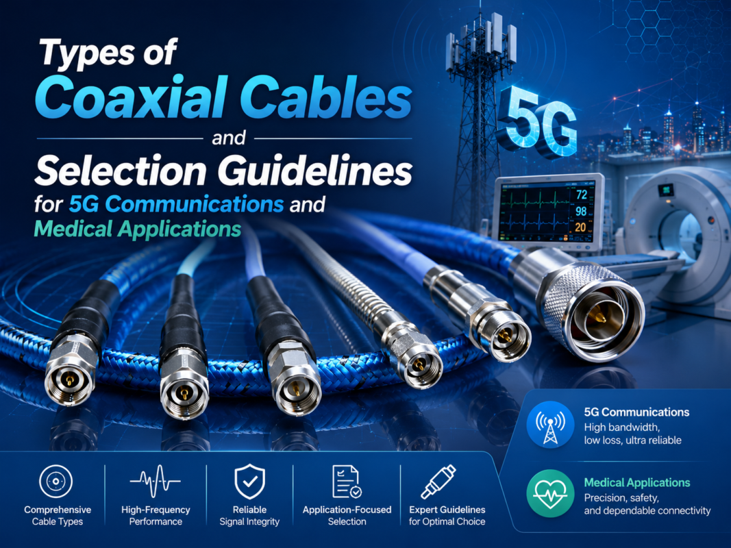
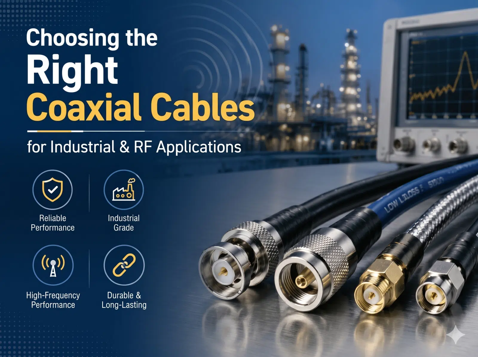
Choosing the Right Coaxial Cables for Industrial & RF Applications
In high electromagnetic noise environments, such as industrial automation, medical equipment, and robotics control, selecting the right coaxial cables directly affects signal transmission stability.
Improper selection can cause electromagnetic compatibility (EMC) failures. It often leads to voltage standing wave ratio (VSWR) degradation, or excessive signal attenuation.
This comprehensive guide outlines the key selection criteria. We focus on electrical parameters, cable classifications, and connector matching specifications.
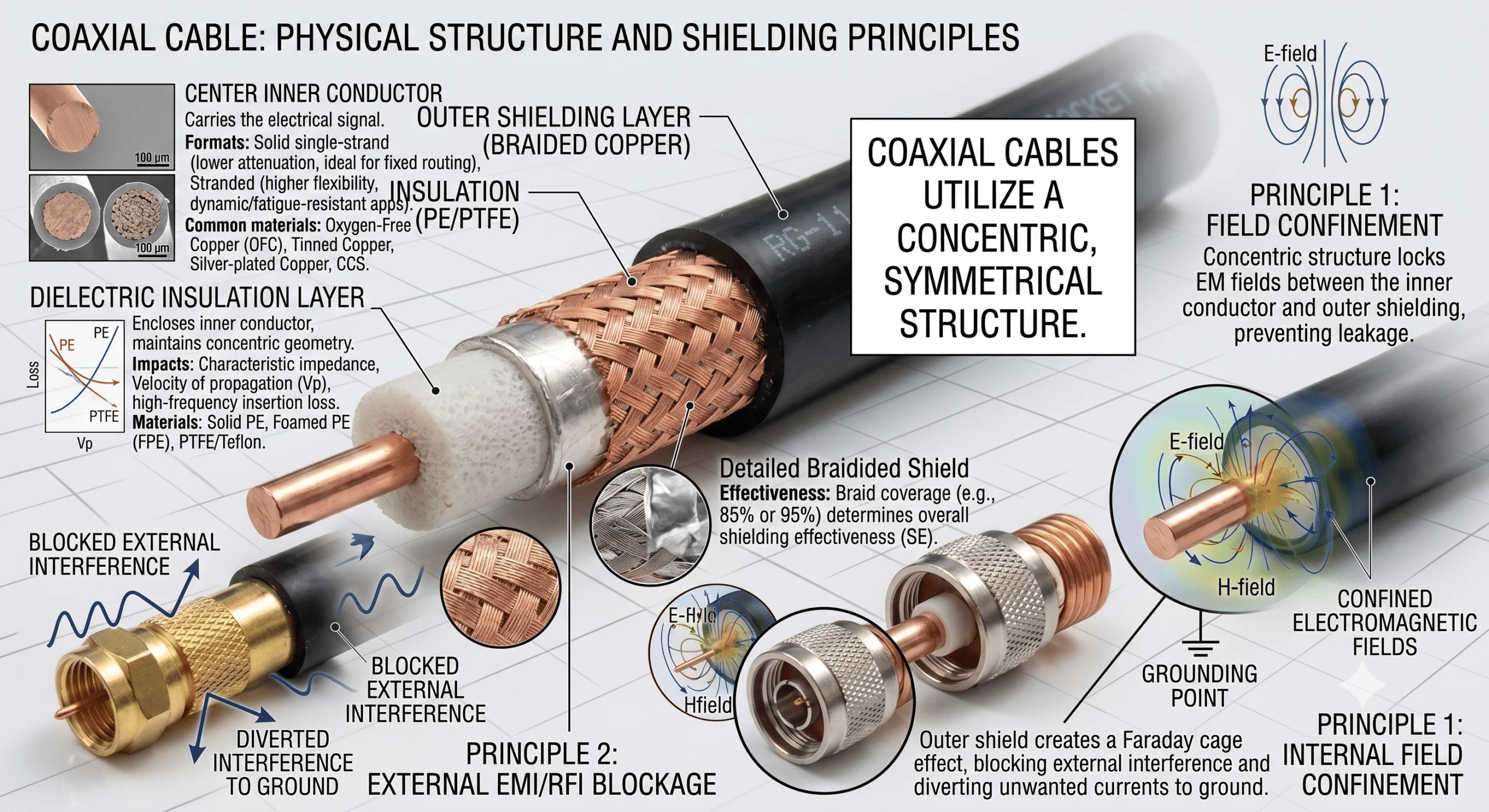
1. Physical Structure and Shielding Principles of Coaxial Cables
Coaxial cables utilize a concentric, symmetrical structure. This design confines the electromagnetic fields generated during signal transmission. These fields remain locked between the inner conductor and the outer shielding layer.
As a result, this specialized architecture minimizes external electromagnetic interference (EMI). It also significantly reduces radiation loss.
Standard industrial-grade coaxial cables consist of four precise layers, from the inside out:
Center Inner Conductor: This layer carries the electrical signal. It is categorized into solid single-strand conductors and stranded conductors. Solid conductors offer lower attenuation, making them ideal for fixed routing. Stranded conductors provide higher flexibility, which is perfect for dynamic, fatigue-resistant applications. Common base materials include oxygen-free copper (OFC), tinned copper, silver-plated copper, or copper-clad steel (CCS).
Dielectric Insulation Layer: This layer encloses the inner conductor tightly. It maintains the critical concentric geometry. Its dielectric constant directly impacts the characteristic impedance, velocity of propagation (Vp), and high-frequency insertion loss of the coaxial cables. Common industrial materials include solid polyethylene (PE), foamed polyethylene (FPE), or polytetrafluoroethylene (PTFE/Teflon).
Outer Shielding Layer / Outer Conductor: This layer completes the electrical signal return path. It effectively blocks external electromagnetic noise. It typically uses a combined structure of aluminum foil and a tinned copper wire braid. The aluminum foil handles high-frequency shielding. The wire braid provides low-frequency shielding. The braid coverage percentage (such as 85% or 95%) directly determines the overall shielding effectiveness (SE).
Outer Jacket: This outermost layer protects the entire cable assembly from physical stress and chemical damage. Common compounds include general-purpose PVC, and wear-resistant, oil-resistant polyurethane (PUR). For harsh environments, weather-resistant polyethylene (PE) or low-smoke zero-halogen (LSZH) flame-retardant materials are widely used.
2. Core Electrical Parameters: Impedance Matching and Attenuation Trends
Before specifying specific cable models, engineers must define two baseline radio frequency (RF) parameters:
1. Characteristic Impedance
The physical dimensions and dielectric insulation materials of coaxial cables determine their inherent impedance. The industry has established two primary standards:
50 Ohm (50 Ω): This is the baseline standard for RF microwave and data communications. It is widely used in wireless base stations, Wi-Fi antenna feedlines, solid-state microwave devices, and RF test equipment. 50 Ω coaxial cables provide an optimal physical balance between RF power handling capability and low signal attenuation.
75 Ohm (75 Ω): This is the standard for high-definition video and long-distance broadcast signal distribution. It is common in medical endoscopes, ultrasound imaging links, closed-circuit television (CCTV), and cable TV networks. 75 Ω coaxial cables offer much lower signal attenuation over long distances for baseband video and broadband signals.
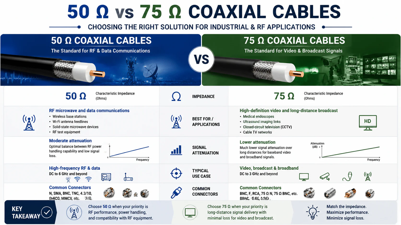
2. Operating Frequency and Nominal Attenuation
Due to the skin effect, high-frequency electrical signals travel primarily along the outer surface of the conductor. As the signal frequency increases, the effective cross-sectional area of the conductor decreases. This behavior accelerates signal attenuation (loss).
Selection requires evaluating the nominal attenuation values. Engineers look at dB/100m (or dB/100ft) at the target operating frequencies. For high-frequency applications above 1 GHz, specialized low-loss coaxial cables are typically required. These cables feature low dielectric loss, larger outer diameters, or silver-plated inner conductors.
3. Major Classifications of Coaxial Cables
Based on impedance, materials, architecture, and application scenarios, commonly utilized coaxial cables are divided into five main categories:

1. RG Series (Standard Radio Guide Coaxial Cables)
The RG series represents the most foundational coaxial cables array. It provides standardized RF interconnection through predefined combinations of metal dimensions and braiding styles.
| Standard Model | Military Specification | Characteristic Impedance | Inner Conductor Specs | Dielectric OD | Cable OD (Approx.) | Typical Application Scenarios |
| RG-6/U | M17/2-RG6 | 75 Ω | 18 AWG Copper-Clad Steel (CCS) | 4.57 mm | 6.90 mm | Satellite antenna access, broadband networks, digital TV |
| RG-8/U | – | 52 Ω | 10 AWG Solid Bare Copper | 7.24 mm | 10.30 mm | High-power radio transmission, RF power-level feedlines |
| RG-11/U | M17/6-RG11 | 75 Ω | 14 AWG Copper-Clad Steel (CCS) | 7.11 mm | 10.30 mm | Remote video transmission, long-distance CATV trunks |
| RG-58 | – | 50 Ω | 20 AWG Solid/Stranded Copper | 2.95 mm | 5.00 mm | General-purpose test jumpers, low-frequency RF connections |
| RG-59/A/U | M17/29-RG59 | 73 Ω | 20 AWG Copper-Clad Steel (CCS) | 3.70 mm | 6.15 mm | Analog CCTV video, short-distance baseband links |
| RG-174 | – | 50 Ω | 26 AWG Stranded Bare Copper | 1.52 mm | 2.80 mm | Internal chassis tight space jumpers, automotive 4G/GPS天线 |
| RG-316 | – | 50 Ω | 26 AWG Silver-Plated CCS | 1.52 mm | 2.60 mm | High-temperature resistant (PTFE jacket), aerospace & high-reliability interconnections |
2. LMR Series (Low-Loss Flexible Coaxial Cables)
The LMR series is engineered to overcome the high-frequency attenuation limits of traditional RG cables. They utilize foamed dielectric materials (PF).
They also integrate a high-performance composite shielding layer, which combines solid aluminum foil with a high-density braided wire net. This architecture minimizes loss and optimizes impedance consistency. Meanwhile, it fully retains the flexible routing characteristics of standard flexible coaxial cables.
| Model Specification | Characteristic Impedance | Center Conductor OD | Insulation Type | Attenuation at 850 MHz (per 100ft) | Attenuation at 1900 MHz (per 100ft) |
| LMR-100 | 50 Ω | 0.46 mm | Solid PE | 22.8 dB | 39.1 dB |
| LMR-200 | 50 Ω | 1.12 mm | Foamed PE | 9.6 dB | 14.6 dB |
| LMR-240 | 50 Ω | 1.42 mm | Foamed PE | 7.2 dB | 11.2 dB |
| LMR-400 | 50 Ω | 2.74 mm | Foamed PE | 3.8 dB | 5.8 dB |
| LMR-600 | 50 Ω | 4.47 mm | Foamed PE | 2.4 dB | 3.8 dB |
3. Hardline Coaxial Cables
Rather than using a wire braiding process, the outer shielding layer consists of a seamless, solid aluminum tube or a corrugated copper tube.
Their solid mechanical structure provides near 100% electromagnetic shielding effectiveness with minimal attenuation. This layout makes them the primary choice for high-power, high-frequency backbone routing.
Typical Applications: Radio transmission tower feedlines, wireless cellular core infrastructure, and radar backbone links.
4. Semi-Rigid and Hand-Formable Precision Coaxial Cables
Semi-Rigid Cables: These cables feature a seamless, solid copper metal tube as the outer jacket. They lack conventional mechanical flexibility. However, they provide unparalleled shielding effectiveness (frequently exceeding 120 dB) alongside superior phase stability.
Hand-Formable Cables: These cables utilize a tin-dipped metal braid. This design preserves the high-frequency microwave performance of semi-rigid configurations. Simultaneously, it allows engineers to manually bend and shape the cable during device assembly.
Typical Applications: Internal microwave module-level jumpers for high-end RF test instruments (such as spectrum analyzers), RF coils for high-precision magnetic resonance imaging (MRI) machinery, and aerospace avionics雷达 sub-assemblies.
5. Twinax and Triax Specialty Shielded Coaxial Cables
Twinaxial Cables: These cables feature two parallel center conductors inside a single outer shield. They are organically suited for differential signaling. This approach effectively balances out capacitive coupling and low-frequency common-mode noise, which significantly minimizes crosstalk. They are commonly deployed in data center high-speed stacking architectures, such as 10G/40G DAC direct attach cables, and avionics buses.
Triaxial Cables: These cables add a second independent insulation layer and a second braided copper shielding layer over standard configurations. The outermost shield is grounded to isolate electrostatic noise. The inner shield functions as a guard path. This setup drives parasitic leakage currents down to the picoampere (pA) scale. They are used primarily in high-precision semiconductor testing, low-level weak signal metrics, and broadcast studio camera links.
4. RF Connectors and Termination Specifications
Selecting the right coaxial cables must be paired with correct RF connector terminations. Any impedance mismatch creates signal reflections. This failure causes severe voltage standing wave ratio (VSWR) degradation.
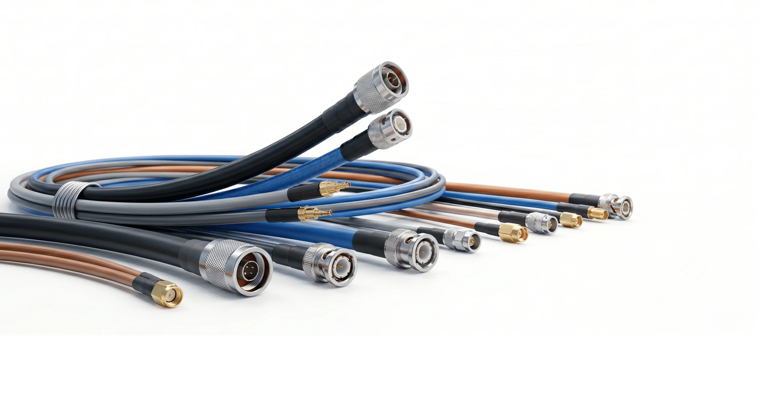
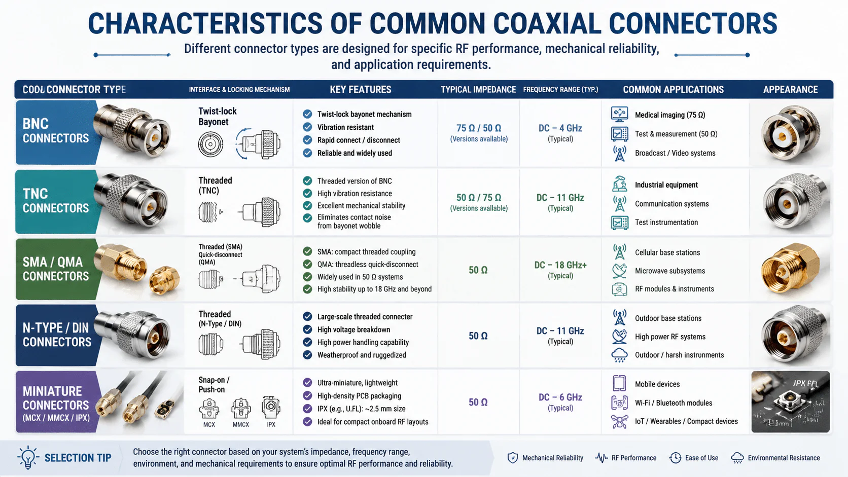
1. Characteristics of Common Coaxial Connectors
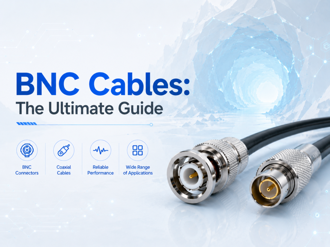
BNC Connectors: These feature a twist-lock bayonet mechanism. They are frequently paired with 75 Ω medical imaging or 50 Ω test configurations. They are well-known for vibration resistance and rapid connection.
TNC Connectors: This is a threaded version of the BNC interface. Once locked, it delivers excellent mechanical stability under high-vibration industrial environments. It completely eliminates the contact noise caused by bayonet wobble.
SMA / QMA Connectors: SMA is a compact threaded coupling connector. It is widely used for 50 Ω cellular base stations and microwave subsystems. It remains highly stable up to 18 GHz and beyond. QMA functions as its threadless, quick-disconnect locking equivalent.
N-Type / DIN Connectors: These are large-scale threaded connectors. They provide high voltage breakdown thresholds and massive power handling capabilities. Weatherproof and ruggedized, they are matching choices for thick outdoor feedlines.
Miniature Connectors (MCX / MMCX / IPX): These are tailored for high-density electronic packaging. Ultra-miniature variations like IPX (e.g., U.FL) measure around 2.5 mm. They are ideal for compact onboard RF layouts.
2. Precision Termination Workmanship
In compliance with the IPC/WHMA-A-620 standard, terminating coaxial cables demands strict precision. Engineers must carefully manage strip lengths, shield folding, crimping, or soldering processes.
Minor geometric distortions create severe impedance discontinuities. These flaws trigger heavy insertion loss. For example, nicks to the inner conductor during stripping, uneven braid folding, deformed crimp sleeves, or excessive soldering temperatures that melt the dielectric core will degrade the signal.
Volume assembly requires automatic stripping equipment to manage structural tolerances alongside 100% testing for VSWR and insertion loss.
5. WIRES Industrial-Grade High-Reliability Coaxial Cables Customization Solutions
In demanding industrial and electronic fields, standard off-the-shelf coaxial cables often fail to balance mechanical lifecycle demands with electrical stability.
As an established cable assembly manufacturer with 28 years of industry experience, WIRES operates strictly under IATF 16949 and ISO 9001 quality management frameworks. We adhere completely to IPC/WHMA-A-620 standard build specifications to deliver premium, custom coaxial cables assemblies:
High-Flex Robot Drag Chain Coaxial Cables: These are engineered for multi-axis robotic arms and continuous-motion automation drag chains. These assemblies utilize ultra-fine multi-strand oxygen-free copper wire for the center inner conductor (e.g., 0.08mm micro-strands). They are coupled with high-durability, tear-resistant polyurethane (PUR) outer jackets. Supporting a tight bend radius of 5D to 8D, they retain stable characteristic impedance across millions of continuous flex cycles. This design successfully prevents copper fractures or insulation splitting.
Anti-Interference Shielded Cable Assemblies: These are optimized for high-noise factory environments densely packed with servo motors and variable frequency drives (VFDs). WIRES delivers custom high-density, multi-layer composite shielding layouts. We combine aluminum foil with double or quadruple tinned copper braids achieving >=85% coverage or higher custom specifications. This setup suppresses high-frequency electromagnetic radiation, eliminating data packet drops in machine vision cameras and minimizing control loop jitter.
Medical-Grade Low Smoke Zero Halogen (LSZH) Coaxial Cables: These are tailored for portable ultrasound probes, endoscopy equipment, and surgical suite devices. Built with jacket compounds capable of enduring aggressive disinfection wipe-downs (such as alcohol or hydrogen peroxide solutions), these assemblies incorporate low-smoke zero-halogen (LSZH) flame retardancy. This choice satisfies rigorous clinical safety regulations and signal integrity standards.
RF Connector Configuration Scope:
WIRES coaxial cables assemblies are customizable in straight, right-angle, or bulkhead form factors. We accommodate precise pairings of plugs (male) and jacks (female).
Supported Interface Styles Include: 1.85mm, 1.0mm, 2.92mm, 10-32, 2.4mm, 7/16 DIN, 4.1/9.5 Mini DIN, Mini SMP, BNC, TNC, F, MCX, MMCX, Mini UHF, N-Type, RCA, QMA, SMB, SMA, SMP, SMC, SSMB, SSMA, UHF, SSMC, U.FL, and UMCX.
Contact the WIRES industrial engineering team today to build custom, high-reliability coaxial cables assemblies designed to secure your system’s signal integrity.