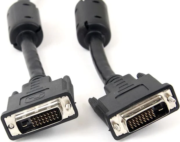
Medical and industrial DVI cables connect legacy or long-life video equipment when the source, display, controller, and installed interface still use DVI. A reliable replacement must match the exact DVI connector, digital or analog signal type, link configuration, pixel clock, EDID and HDCP behavior, cable route, retention, EMC environment, and equipment validation requirements.
DVI remains useful in imaging workstations, industrial HMIs, machine-vision systems, test equipment, control rooms, and service replacements. However, a DVI cable alone cannot establish medical-device compliance, diagnostic image quality, EMC compliance, or complete-system reliability. Those outcomes depend on the entire approved equipment configuration and its verification.
Digital Visual Interface was defined by the Digital Display Working Group in the DVI Revision 1.0 specification. Digital DVI uses Transition Minimized Differential Signaling (TMDS) to transmit video data and a clock between a source and a display. The connector family also includes versions that carry analog video.
| DVI type | Signal capability | Typical connector contacts | Selection note |
|---|---|---|---|
| DVI-D single-link | Digital only, one TMDS link | 18+1 | Confirm source and display timing, EDID, and connector keying |
| DVI-D dual-link | Digital only, two TMDS links | 24+1 | Both devices and the cable must support the required dual-link timing |
| DVI-I single-link | Digital plus analog contacts | 18+5 | The presence of analog pins does not prove the source generates analog video |
| DVI-I dual-link | Digital dual-link plus analog contacts | 24+5 | Verify the actual active signal mode and device support |
| DVI-A | Analog only | 12+5 | Used for analog compatibility, not digital DVI-D equipment |
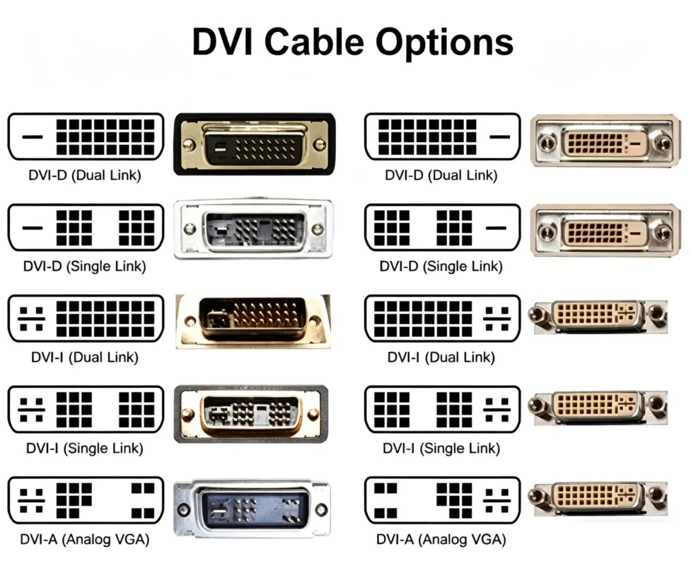
Connector appearance is not enough. Record the exact source port, display port, active digital or analog mode, link requirement, and mating orientation. A DVI-I receptacle may accept more plug types mechanically, but the equipment must still generate and receive the required signal.
For broader interface comparisons, see the AV cable selection guide and WIRES display cable assemblies.
A single digital DVI link contains three TMDS data pairs plus a clock pair. A dual-link interface adds three more data pairs. Under the DVI 1.0 design, the commonly cited maximum single-link pixel clock is 165 MHz; dual-link operation combines two links and is commonly associated with an aggregate 330 MHz pixel-clock capability.
Common reference modes include approximately 1920 × 1200 at 60 Hz for single-link and 2560 × 1600 at 60 Hz for dual-link. These are not universal guarantees. Blanking intervals, color format, bit depth, transmitter and receiver limits, reduced-blanking support, cable loss, adapters, and display timing determine whether a specific mode works.
| Requirement | Why it matters | Evidence to collect |
|---|---|---|
| Active resolution and refresh rate | Determines pixel-clock demand | Source output modes and display timing list |
| Single- or dual-link operation | Changes the number of active TMDS pairs | Equipment manual, port pinout, and verified working cable |
| EDID/DDC behavior | Controls display identification and mode negotiation | EDID capture, system logs, or equipment service data |
| HDCP requirement | Protected content may require compatible source, repeater, and display behavior | Device specifications and end-to-end test |
| Cable route and adapters | Add loss, discontinuities, and compatibility boundaries | Installed route, connector count, and adapter part numbers |
Long-life equipment may retain DVI because the video controller, display electronics, software image, approved accessories, mechanical panel, and service documentation were designed around that interface. Replacing DVI with a newer connector may require active conversion, firmware changes, new EMC testing, mechanical redesign, or regulatory assessment.
| Environment | Typical DVI role | Primary cable risks |
|---|---|---|
| Medical imaging workstation | Video connection between a controller and approved display | Display timing, EDID, cleaning exposure, grounding, EMC, and configuration control |
| IVD or laboratory analyzer | Internal or external user-interface display | Reagent or cleaner exposure, service routing, connector retention, and equipment EMC |
| Industrial HMI | Controller-to-panel display link | Vibration, cabinet routing, motor-drive noise, temperature, and maintenance access |
| Machine vision | Display or processing-monitor output rather than camera transport in many systems | Resolution, timing, installed length, grounding, and conversion compatibility |
| Test and measurement | Legacy instrument or workstation display output | Frequent service, adapter chains, connector wear, and configuration traceability |
For equipment-side medical wiring, review medical equipment harnesses and the IVD cable assembly design guide. Industrial projects can also reference industrial wire harnesses and the industrial AV cable assembly guide.
DVI digital video depends on controlled differential paths. Cable performance is influenced by pair geometry, conductor size, dielectric material, twist consistency, shielding, connector transitions, pair-to-pair skew, insertion loss, return loss, crosstalk, and the source and receiver signal margin. No single shield percentage or conductor material guarantees a stable image.
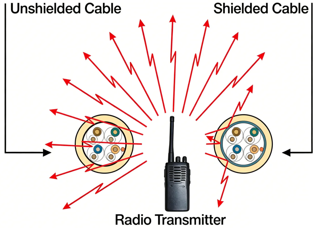
Designs may use foil around individual high-speed pairs, an overall foil, a braid, drain conductors, or combinations of these elements. The correct construction depends on the channel, enclosure, grounding strategy, motion, diameter limit, and EMC plan. Foil can provide high-frequency coverage; braid can improve mechanical robustness and lower-frequency shielding, but effectiveness depends on coverage, transfer impedance, connector bonding, and installation.
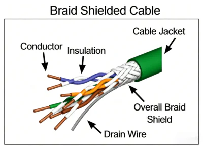
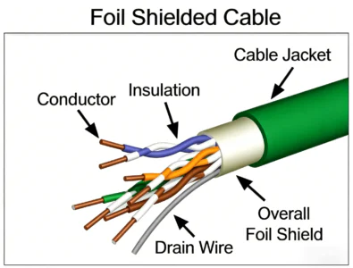
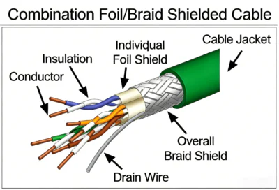
Shield termination is part of the design. A high-quality cable can still fail EMC testing if the connector shell, panel bond, pigtail, enclosure, chassis path, or adjacent power routing is incorrect. Conversely, connecting every shield identically without considering the equipment grounding architecture can create unwanted current paths.
These are design controls, not proof of compliance. IEC 60601-1-2 may be relevant to medical electrical equipment, IEC 61326 may be relevant to laboratory or measurement equipment, and industrial EMC standards may apply to machinery or control systems. The exact product, intended use, market, edition, immunity level, emissions class, and test configuration must be defined. Mentioning a standard does not state that WIRES or a cable is certified to it.
DVI connectors are relatively large and can place leverage on a panel or PCB connector. Medical carts, industrial cabinets, and serviceable modules need mechanical controls that protect the interface during installation, vibration, cleaning, and maintenance.
| Design element | Questions to specify |
|---|---|
| Retention | Are thumbscrews, jack screws, panel brackets, or captive hardware required? |
| Connector orientation | What cable-exit direction avoids interference and connector side load? |
| Strain relief | Where is bending transferred from the connector to the cable jacket? |
| Flexing | Is movement occasional service motion, repeated cart motion, or continuous machine motion? |
| Panel integration | Is the interface cable-mounted, panel-mounted, bulkhead-mounted, or PCB-mounted? |
| Service identification | Are source/display ends, direction, equipment ID, and approved replacement number labeled? |
| Cleaning | Which agents, wipe methods, contact time, and cable areas are exposed? |
A molded backshell can provide strain relief and controlled geometry, but it does not automatically make a DVI assembly waterproof, sterilizable, medical grade, or suitable for continuous flexing. Those attributes require defined materials, interfaces, tests, and acceptance limits.
| Exposure | Design response | Evidence needed |
|---|---|---|
| Cleaning agents | Select jacket, label, overmold, and seal materials for the exact chemical and wipe process | Material data, concentration, temperature, contact time, and compatibility test |
| Oil or coolant | Use a construction rated for the identified fluid and route away from pooling | Fluid identity, exposure method, and post-exposure acceptance criteria |
| Temperature | Check conductor, dielectric, jacket, connector, and equipment limits together | Normal, peak, cold-start, storage, and nearby-component conditions |
| Vibration | Control connector retention, support spacing, mass, and strain relief | Equipment vibration profile, mounting, duration, and functional monitoring |
| Repeated movement | Define a flex construction and guide the bend path | Bend radius, travel, speed, torsion, cycle objective, and failure criteria |
| Low smoke or flame requirement | Select an exact listed or qualified material system | Applicable standard, revision, test method, and product evidence |
Terms such as “medical grade,” “industrial grade,” “halogen free,” “oil resistant,” and “flame retardant” need an exact material, standard, test method, specimen, and scope. They should not be inferred from jacket color or marketing language.
| Connection | Passive or active? | Important limitation |
|---|---|---|
| DVI-D to HDMI | Often passive for compatible digital TMDS video | Connector adaptation does not guarantee audio, HDCP, EDID, resolution, or device compatibility |
| DVI-I to VGA | Passive only when the source provides analog video on the DVI-I analog contacts | A DVI-I connector does not prove the source outputs analog video |
| DVI-D to VGA | Requires active digital-to-analog conversion | Direction, power, timing, image quality, and supported modes must be verified |
| DisplayPort source to DVI display | Passive may work with a compatible dual-mode source for supported modes; otherwise active | Direction, single/dual-link requirement, pixel clock, power, and adapter chipset matter |
| DVI source to DisplayPort display | Typically active conversion | A passive connector cable does not convert DVI into DisplayPort protocol |
| DVI over fiber or extender | Active system | Direction, power, EDID, HDCP, latency, resolution, environmental rating, and serviceability require validation |
For compact HDMI equipment interfaces, compare the industrial and medical Micro HDMI guide. Do not replace an approved DVI channel with HDMI, DisplayPort, VGA, or an extender solely because the connectors can be adapted.
The DVI specification does not provide one universal passive cable length that works for every resolution and device pair. Usable length depends on pixel clock, conductor and dielectric construction, pair skew, attenuation, connector transitions, source amplitude, receiver equalization, adapters, routing, temperature, and EMC conditions.
Instead of promising a fixed distance:
| Verification | Purpose | Record |
|---|---|---|
| Pinout and continuity | Confirm every required signal, ground, shield, and DDC path | Tester program, fixture revision, and result |
| Connector inspection | Check keying, contacts, shell, hardware, strain relief, and workmanship | Drawing criteria and inspection record |
| Signal-mode test | Confirm the required resolution, refresh rate, link mode, and device pair | Source/display IDs, timing, firmware, and pass criteria |
| EDID and startup | Find intermittent detection or negotiation failures | Power sequence, restart cases, logs, and recovery behavior |
| EMC system test | Evaluate emissions and immunity in the approved equipment configuration | Applicable standard, edition, setup, operating mode, and report |
| Mechanical test | Evaluate retention, vibration, flexing, or service handling | Profile, mounting, samples, cycles or duration, and acceptance limits |
| Material compatibility | Assess cleaner, oil, coolant, heat, or humidity exposure | Exact agent, condition, specimen, and post-test inspection |
Qualification testing and production acceptance are different. A design may be qualified using environmental and EMC tests, while production acceptance may use continuity, pinout, workmanship, dimensional, and functional checks defined by the approved control plan. Do not claim universal 100% high-voltage, signal-integrity, or environmental testing unless the purchase specification requires it and records are available.
WIRES’ process and services and customized process explain the normal development path for equipment cable assemblies. Review available certification information separately; this article does not state that every DVI assembly is certified for a medical or industrial system.
It can be suitable when the approved source, display, mechanical interface, EMC design, software configuration, and risk controls use DVI. The complete medical electrical system—not the cable alone—must meet the applicable safety, essential-performance, EMC, and regulatory requirements.
DVI-D carries digital signals only. DVI-I includes digital contacts plus analog contacts. A DVI-I port does not guarantee that the device generates both signal types, so confirm the equipment documentation and active mode.
Use dual-link only when the source and display require and support the additional TMDS link for the intended timing. Connector pin count, equipment specification, pixel clock, and an end-to-end test should confirm the requirement.
The DVI specification is primarily a video interface, so audio should not be assumed. Some HDMI-compatible sources and adapters may transport audio in particular configurations, but the source, adapter, display, EDID, and operating mode must all support it.
There is no reliable universal maximum. The working distance depends on pixel clock, cable loss and skew, source and receiver margin, adapters, routing, temperature, and EMC conditions. Validate the exact device pair and operating mode over the installed route.
No. Passive adaptation requires analog video on the DVI-I analog contacts. DVI-D is digital only and requires active conversion to VGA. Direction, supported timing, power, and image quality must be checked.
Provide photos and part numbers for both ports, the original cable, source and display models, operating resolution and refresh rate, single- or dual-link requirement, length, routing, retention, environment, and validation needs.
A dependable medical or industrial DVI replacement comes from matching the interface, timing, mechanical design, materials, EMC architecture, and test plan to the real equipment. Send the source and display details, original cable information, drawings, environment, and required operating modes through the WIRES contact page for a cable-assembly review.
 English English
 Vietnamese
 Indonesian
 Arabic
 Spanish